Liquid holding container and liquid consuming apparatus

a technology of liquid consuming apparatus and liquid holding container, which is applied in printing and other directions, can solve the problems of liquid not being able to be held, liquid cannot be refilled, and it is difficult for air to intermix with the moving liquid

Inactive Publication Date: 2013-07-25
SEIKO EPSON CORP
View PDF4 Cites 3 Cited by
  • Summary
  • Abstract
  • Description
  • Claims
  • Application Information

AI Technical Summary

Benefits of technology

[0009]It is an advantage of some aspects of the invention to provide a technique that makes it possible to refill a liquid even in a liquid holding container that utilizes the principle of Mariotte's bottle.
[0011]In the liquid holding container according to the invention, the injection opening is sealed in an airtight state, and in this state, the liquid surface of the liquid attempts to drop under its own weight, creating a negative pressure in the interior; the liquid is held within the liquid holding container by this negative pressure. Meanwhile, two liquid holding sections (the first liquid holding section and the second liquid holding section) that communicate with each other are provided in the liquid holding container, and the divider member provided in the area where the two sections communicate with each other makes it possible to switch between a state in which the first liquid holding section and the second liquid holding section communicate with each other and a state in which the first liquid holding section and the second liquid holding section are separated from each other in an airtight state.
[0012]If the first liquid holding section and the second liquid holding section are separated from each other in an airtight state, the negative pressure within the first liquid holding section can be maintained even if the injection opening is opened. Accordingly, if the liquid is injected into the second liquid holding section from the injection opening and the first liquid holding section and the second liquid holding section are put into a communicative state after the injection opening is closed in an airtight state, the liquid holding container can be refilled with the liquid while maintaining the negative pressure.
[0014]In this case, when the divider member is opened and first liquid holding section and the second liquid holding section are caused to communicate after the second liquid holding section has been filled with the liquid, the liquid that flows from the second liquid holding section to the first liquid holding section and the liquid that flows from the first liquid holding section to the second liquid holding section move through separate channels. Accordingly, the movement of the liquid is not inhibited by the movement of air, and thus the liquid can move quickly; as a result, the refilling of the liquid holding container with the liquid can be completed quickly. In addition, because the channel through which air moves and the channel through which the liquid moves are separate, it is difficult for air to intermix with the moving liquid. As a result, the occurrence of issues caused by bubbles in the liquid can be suppressed.

Problems solved by technology

However, a liquid holding container that utilizes the principle of Mariotte's bottle has a problem in that the liquid cannot be refilled by providing an injection opening.
In other words, the negative pressure within the liquid holding container will be released if the injection opening is opened in order to refill the liquid, and there has thus been a problem in that the liquid cannot be held within the liquid holding container by utilizing the principle of Mariotte's bottle.
In addition, because the channel through which air moves and the channel through which the liquid moves are separate, it is difficult for air to intermix with the moving liquid.

Method used


Image

  • Liquid holding container and liquid consuming apparatus
  • Liquid holding container and liquid consuming apparatus
  • Liquid holding container and liquid consuming apparatus

Examples


Embodiment Construction

[0025]Hereinafter, an embodiment of the invention will be described according to the following order in order to clarify the content of the invention.

[0026]Apparatus Configuration

[0027]Method for Filling Ink Tank with Ink

[0028]Variations[0029]First Variation[0030]Second Variation[0031]Third Variation

Apparatus Configuration

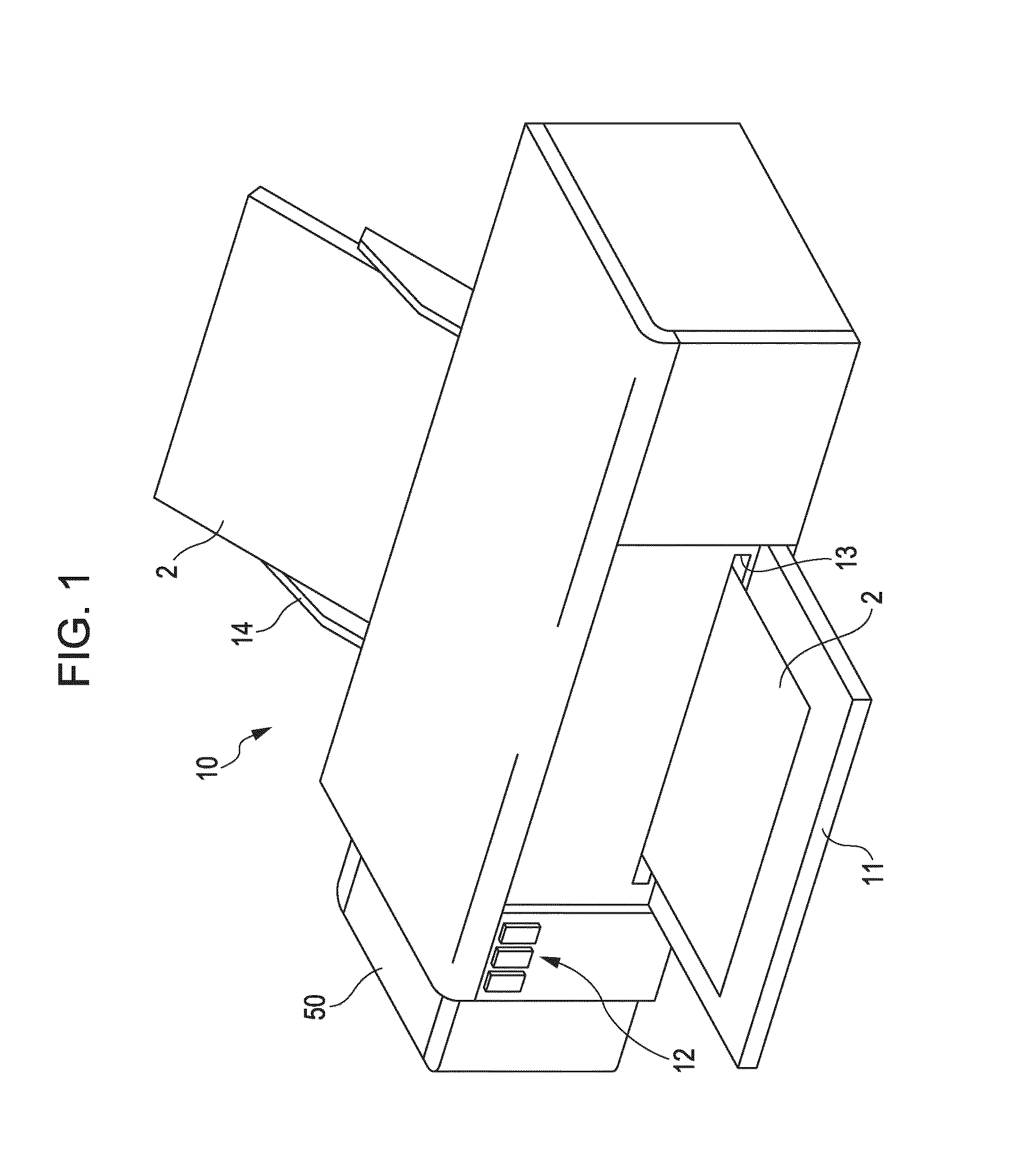
[0032]FIG. 1 is a schematic diagram illustrating the general configuration of a liquid consuming apparatus according to this embodiment, using what is known as an ink jet printer as an example. An ink jet printer 10 has an approximately box-shaped outer shape; a front cover 11 is provided in essentially the center of the front surface of the printer, and a plurality of operation buttons 12 are provided to the left thereof. The front cover 11 is axially supported on its lower end, and a long, thin paper discharge port 13 from which print paper 2 is discharged is exposed when the upper end of the front cover 11 is tilted forward. In addition, a paper supply tray 14 i...


PUM


Abstract

In a liquid holding container configured so that a first liquid holding section in which a liquid outflow opening and an air intake opening are provided communicates with a second liquid holding section in which a liquid injection opening is provided, a divider member, capable of switching between a state in which the first liquid holding section and the second liquid holding section communicate and a state in which the stated sections are separated from each other in an airtight state, is provided in an area where the first liquid holding section and the second liquid holding section communicate with each other. If the first liquid holding section and the second liquid holding section are separated from each other in an airtight state, a negative pressure within the first liquid holding section can be maintained even if the injection opening is opened.

Description

[0001]Priority is claimed under 35 U.S.C. §119 to Japanese Application No. 2012-012760 filed on Jan. 25, 2012 which is hereby incorporated by reference in its entirety.BACKGROUND[0002]1. Technical Field[0003]The present invention relates to techniques for supplying a liquid to a liquid consuming apparatus.[0004]2. Related Art[0005]Liquid consuming apparatuses (for example, ink jet printers) that eject a liquid from an ejecting head are known. The liquid ejected from the ejecting head is held in a liquid holding container, and the liquid held in the liquid holding container is supplied to the ejecting head via a connection tube or the like.[0006]The principle known as “Mariotte's bottle” is sometimes used for the purpose of supplying only the amount of liquid to be ejected from the liquid holding container to the ejecting head. With a liquid holding container using this principle, a liquid supply opening and an air intake opening are provided in a base area of the liquid holding cont...

Claims


Application Information

Patent Timeline
Patent Type & Authority Applications(United States)
IPC IPC(8): B41J2/175
CPCB41J2/17509B41J2/17556
Inventor KOBASHI, MASARUYAMADA, YOICHI
Owner SEIKO EPSON CORP
Why Eureka
Try Eureka