Resorptive intramedullary implant between two bones or two bone fragments

Active Publication Date: 2013-07-25
STRYKER EURO OPERATIONS HLDG LLC
View PDF5 Cites 25 Cited by
  • Summary
  • Abstract
  • Description
  • Claims
  • Application Information

AI Technical Summary

Benefits of technology

[0009]From this state of the art, the object that the invention proposes to attain is further improving the anchor and the stability

Problems solved by technology

However, these solutions are not adapted for the

Method used


Image

  • Resorptive intramedullary implant between two bones or two bone fragments
  • Resorptive intramedullary implant between two bones or two bone fragments
  • Resorptive intramedullary implant between two bones or two bone fragments

Examples


Embodiment Construction

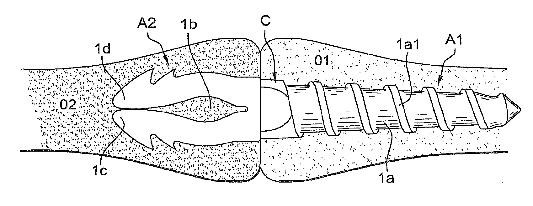
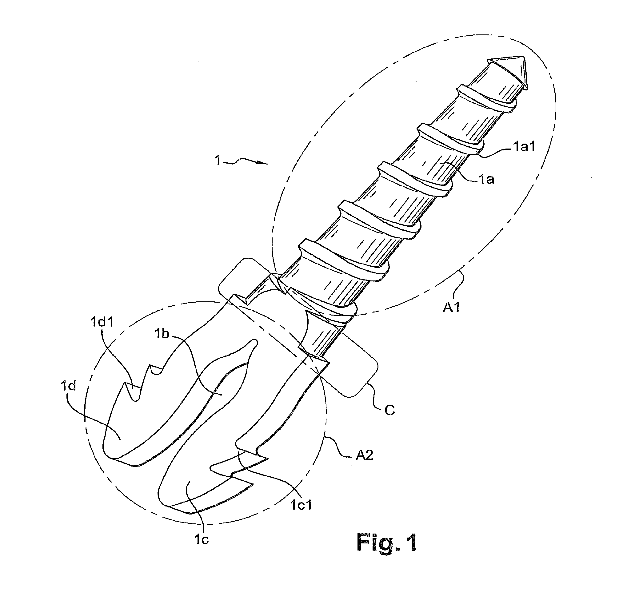
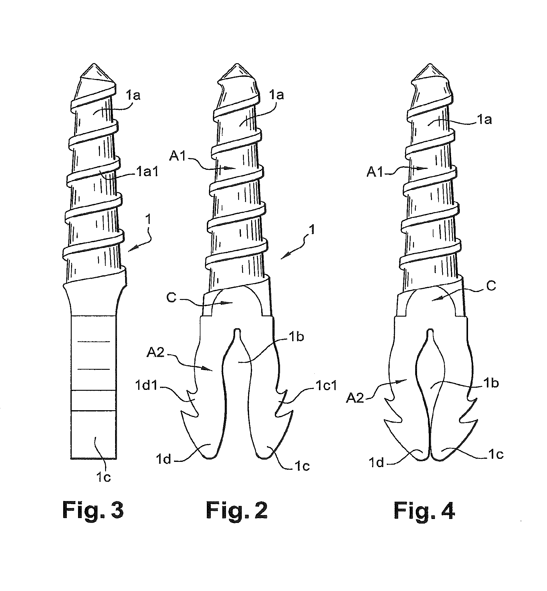
[0024]The implant according to the invention has a one-piece body 1 of elongated shape and having a first proximal zone A1 and a second distal zone A2. The entire implant body is made of a resorptive material whose mechanical properties are determined for the implant to be resorbed in no less than about 6 months. In one embodiment, the implant is composed of lactic acid polymer or copolymer (PLA, PGA . . . ).

[0025]As will be described later in the description, the zones A1 and A2 have anchor formations for the respective bone parts. Taking into account the specific characteristics of the resorptive material and to attain the given object of anchor and stability, the zone A1 is of a cylindrical shape section whereas the other zone A2 is flat.

[0026]The zone A1 has a generally cylindrical outer surface 1a with a limited taper toward its free end. The surface 1a has a helical rib forming a screwthread 1a1.

[0027]The zone A2 is flat and has substantially in its center, an opening 1b adapt...


PUM

PropertyMeasurementUnit
Angleaaaaaaaaaa
Angleaaaaaaaaaa
Deformation enthalpyaaaaaaaaaa

Abstract

The invention relates to an intramedullary implant for use between two bones or two bone fragments. The implant includes a single-piece body having a generally elongate shape and having, at each end, areas for anchoring to the bone portions in question, characterized in that one of said areas has a generally cylindrical shape while the other area has a flat cross-section.

Description

CROSS-REFERENCE TO RELATED APPLICATIONS[0001]This application is continuation of U.S. patent application Ser. No. 12 / 918,105, filed on Oct. 29, 2012, which is a US national phase of PCT application PCT / FR2009 / 051658, filed Sep. 2, 2009, published Mar. 18, 2010 as 2010 / 029246, and claiming the priority of French Patent Application No. 0856035 itself filed Sep. 9, 2008, whose entire disclosures are herewith incorporated by reference.FIELD OF THE INVENTION[0002]The invention relates to the technical field of orthopedic implants, particularly for arthrodesis and osteosynthesis.[0003]More particularly, the invention relates to an intramedullary implant for arthrodesis between two bone parts or osteosynthesis between two bone fragments, particularly in the case of the hand or foot.BACKGROUND OF THE INVENTION[0004]Different solutions have been proposed to achieve these functions.[0005]For example, a solution comes from the teaching of patent application FR 2,884,406 [US 2008 / 0177262], of w...

Claims


Application Information

Patent Timeline
IPC IPC(8): A61B17/72
CPCA61B17/68A61B17/7233A61B17/7225A61B17/7266A61B17/7283A61B17/8605A61F2/4225A61F2/4241A61F2002/30062A61F2002/30563A61F2002/30622A61F2002/3085A61F2002/30878A61F2210/0004A61B17/7208
Inventor PRANDI, BERNARDAUGOYARD, MARCLEDERMANN, THOMASMEUSNIER, TRISTANPEYROT, JACQUESFELLMANN, JUDITH
Owner STRYKER EURO OPERATIONS HLDG LLC
Why Eureka
Try Eureka