Toy gun

a technology for toys and guns, applied in the field of toys and guns, can solve the problems of impaired design of the clamp lever portion 30 and achieve the effects of easy replacement, simple operation, and easy pinching of the operation portion

Active Publication Date: 2013-08-01
MARUZEN
View PDF3 Cites 6 Cited by
  • Summary
  • Abstract
  • Description
  • Claims
  • Application Information

AI Technical Summary

Benefits of technology

[0012]According to the invention, the following takes place when a user of the toy gun moves the operation portion to slide the abutment portion along the sliding surface: the fulcrum portion is broken away from the cartridge housing portion and the first arm element rotates. The distance between the abutment portion and the operation portion is longer than the distance between the abutment portion and the fulcrum portion; therefore, the user only has to apply small force. Since the operation portion is brought far away from the cartridge housing portion, a user can easily pinch the operation portion. Therefore, it is possible to firmly attach a gas cartridge to the toy gun through simple operation and the gas cartridge can be easily replaced. It is unnecessary to provide the first arm element with a part to be pinched by a user. For this reason, the design of the toy gun is not impaired.

Problems solved by technology

However, if the tab portion is provided, the design of the clamp lever portion 30 will be impaired.

Method used


Image

  • Toy gun
  • Toy gun
  • Toy gun

Examples


Embodiment Construction

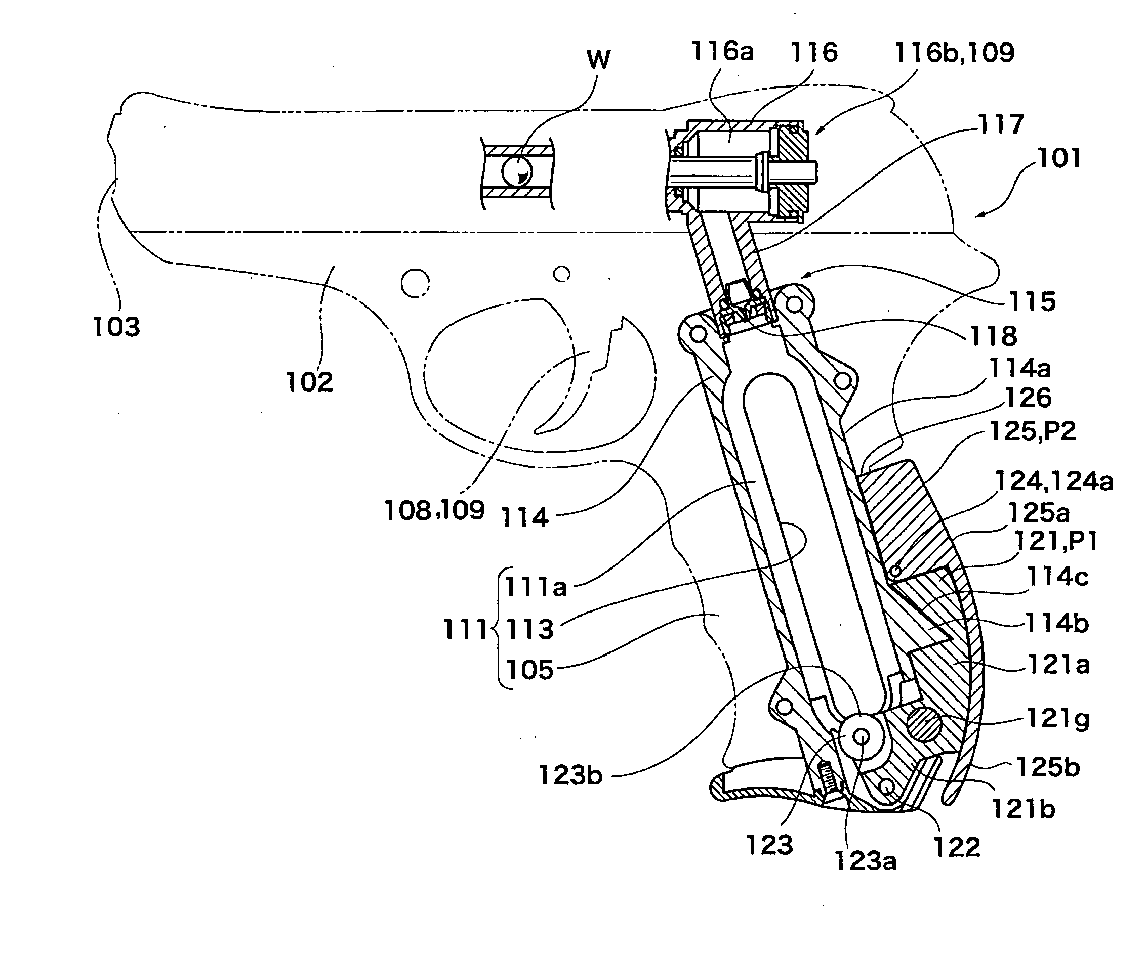
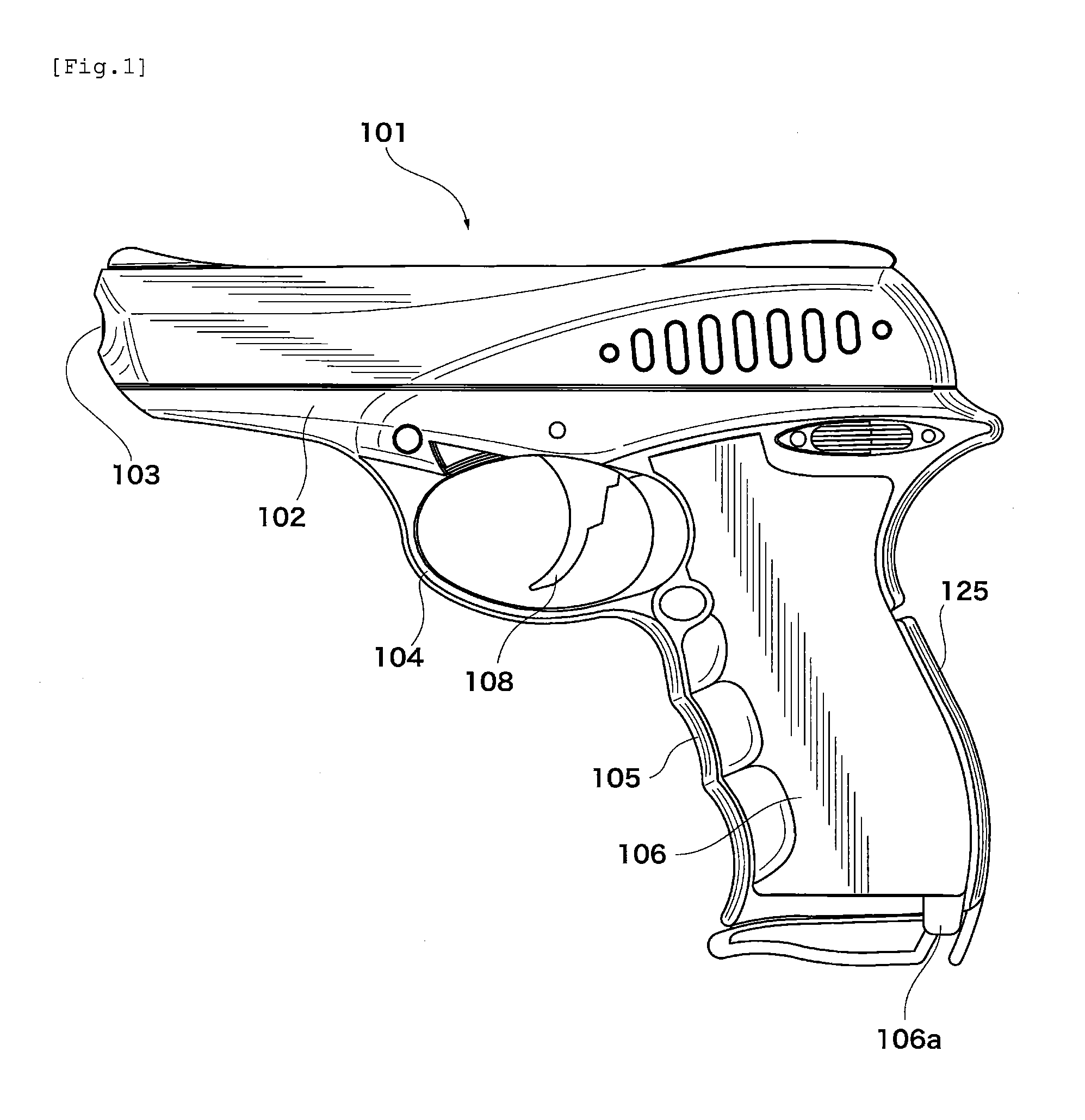
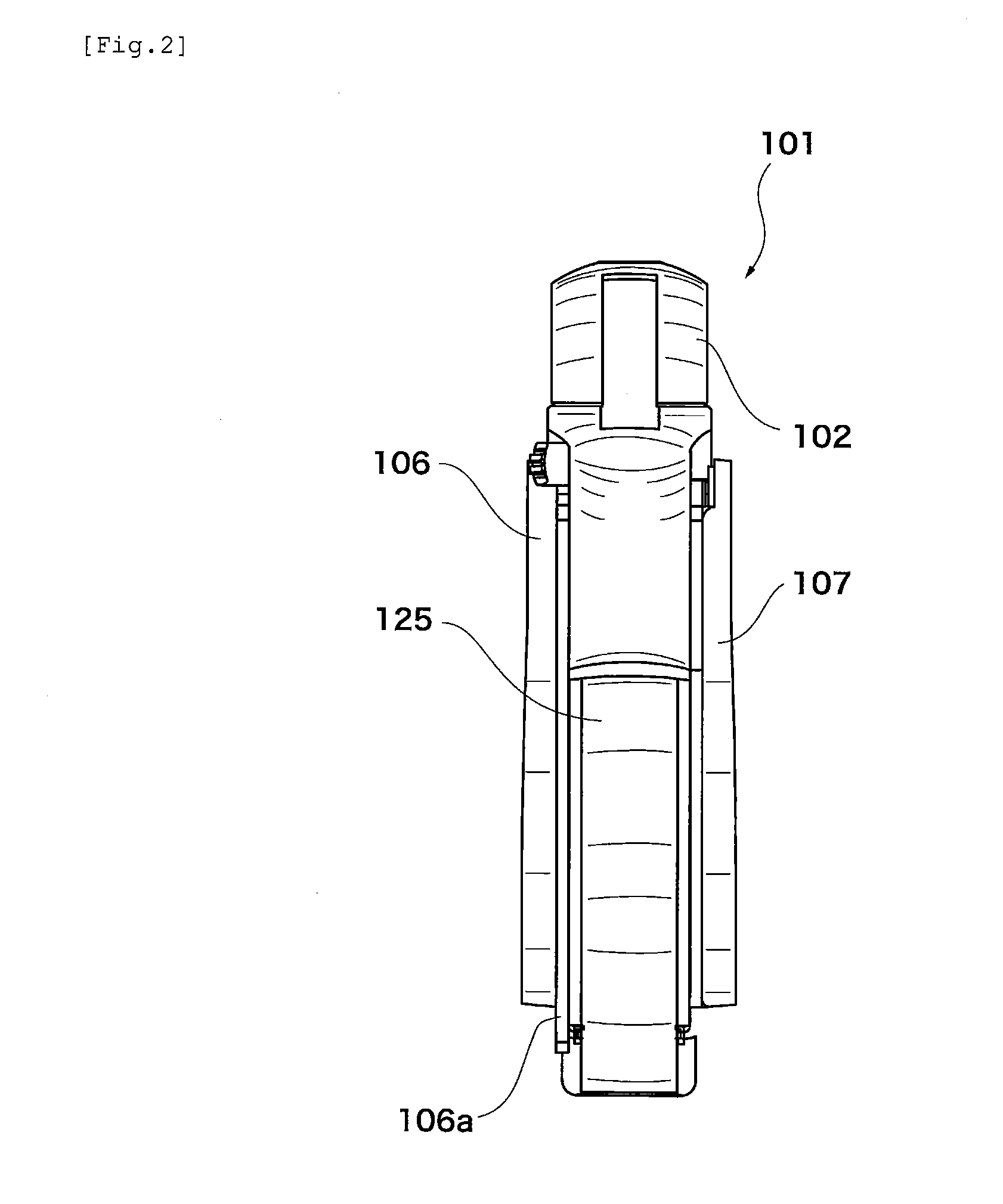
[0027]A description will be given to an embodiment with reference to FIG. 1 to FIG. 14. FIG. 1 is a side view of a toy gun 101. FIG. 2 is a side view of the rear side of the toy gun 101. In the following description, the side surface of the rear side of the toy gun 101 will be taken as a front face and the side of the toy gun 101 shown in FIG. 1 may be designated as left side.

[0028]The primary shape of the toy gun 101 is formed of a main frame 102. The main frame 102 forms each part, such as a muzzle 103, a trigger guard 104, and a grip 105. A left grip panel 106 is installed on the left side surface of the grip 105. A right grip panel 107 is installed on the right side surface of the grip 105.

[0029]The left grip panel 106 can be freely attached to and detached from the grip 105. A tab portion 106a is provided at the lower part of the left grip panel 106. The tab portion 106a is protruded downward from the lower side of the left grip panel 106. A user of the toy gun 101 can pinch th...


PUM


Abstract

A gas cartridge is firmly attached to a toy gun and the gas cartridge is replaced through simple operation. The gas cartridge is filled therein with compressed gas for firing a bullet. A cartridge housing portion slidably holds the circumferential surface of the gas cartridge. The lid portion of the gas cartridge housed in the cartridge housing portion is coupled to a cartridge attachment portion. A clamp arm has a roller and an extended portion and can be freely rotated around a rotation shaft. When the clamp arm is rotated, the roller presses the bottom portion of the gas cartridge in the cartridge housing portion. A raising lever has an abutment portion and is coupled to the extended portion so that the raising lever can be rotated around an installation shaft. When the raising lever is moved, the abutment portion slides on the sliding surface and rotates the clamp arm.

Description

BACKGROUND OF THE INVENTION[0001]1. Field of the Invention[0002]The present invention relates to a toy gun to which a gas cartridge filled with compressed gas can be attached and which fires a bullet utilizing the injection pressure of the compressed gas.[0003]2. Description of Related Art[0004]Toy guns to which a gas cartridge filled with compressed gas of carbon dioxide or the like can be attached and which fire a bullet utilizing the injection pressure of the compressed gas conventionally exist. The compressed gas is discharged according to operation with the trigger provided in the toy gun and hits a bullet loaded in the toy gun to fire the bullet. In such a toy gun, the following are both important: that a gas cartridge is reliably attached and does not come off and that a gas cartridge can be easily replaced.[0005]FIG. 4, FIG. 6, FIG. 8, and FIG. 10 in the specification of U.S. Pat. No. 7,290,539 will be referred to. A cartridge housing portion 2 for housing a high-pressure ga...

Claims


Application Information

Patent Timeline
Patent Type & Authority Applications(United States)
IPC IPC(8): F41B11/06
CPCF41B11/62
Inventor MAEDA, TETSUO
Owner MARUZEN
Why Eureka
Try Eureka