Tents and support frames for tents

a technology for supporting frames and tents, which is applied in the direction of tents/canopies, buildings, constructions, etc., can solve the problems of increasing the erection/striking time of tent frames, cumbersome collapse or erecting of frames, and time and often knowledge/skills they need to erect correctly, so as to reduce friction and reduce the amount of effort. , the effect of reducing the wear of rop

Inactive Publication Date: 2013-08-01
NBC SERVICE
View PDF3 Cites 25 Cited by
  • Summary
  • Abstract
  • Description
  • Claims
  • Application Information

AI Technical Summary

Benefits of technology

[0010]By constraining the ridge beam portions to pivot about a fixed axis, the amount of play in the tent frame, once erected, can be considerably reduced compared to a system in which the ridge beam portions can pivot in more than one sense.
[0016]Advantageously, such a support frame according to any of the aforementioned aspects of the invention may comprise a plurality of permanently interconnected beams, which avoids the need for users to correctly identify and connect the various beams at the correct locations. Furthermore, since the beams are pivotally interconnected, the support frame can be folded in on itself to occupy a vastly reduced volume when in a folded state as compared to an erected state.
[0026]The guide means is / are provided to ensure that the rope or ropes slide relative to the support frame at fixed, or substantially fixed points thereon. The guide means may comprise any one or more of a block, a ring or a channel. Most preferably, the guide means comprises a pulley block to reduce friction, which reduces rope wear and the amount of effort needed to hoist the tent liner into position. The locking means may comprise a cleat or an eyelet to which a rope can be tied.

Problems solved by technology

A drawback of known tents is the time and often knowledge / skill they take to erect correctly, which drawback is particularly relevant to large tents and marquees.
This system requires a user to be able to access the elevated ridge to effect collapsing, which can be cumbersome and awkward in a real-life situation, and which can increase the erection / striking time of the tent frame.
The ridge beams pivot horizontally at an elevated position, making the frames cumbersome to collapse or erect.
Collapsing of the elevated ridge beam can be difficult, and the addition of hinges in the rafters can lead to undesirable play in the structure, making it less rigid.

Method used


Image

  • Tents and support frames for tents
  • Tents and support frames for tents
  • Tents and support frames for tents

Examples


Embodiment Construction

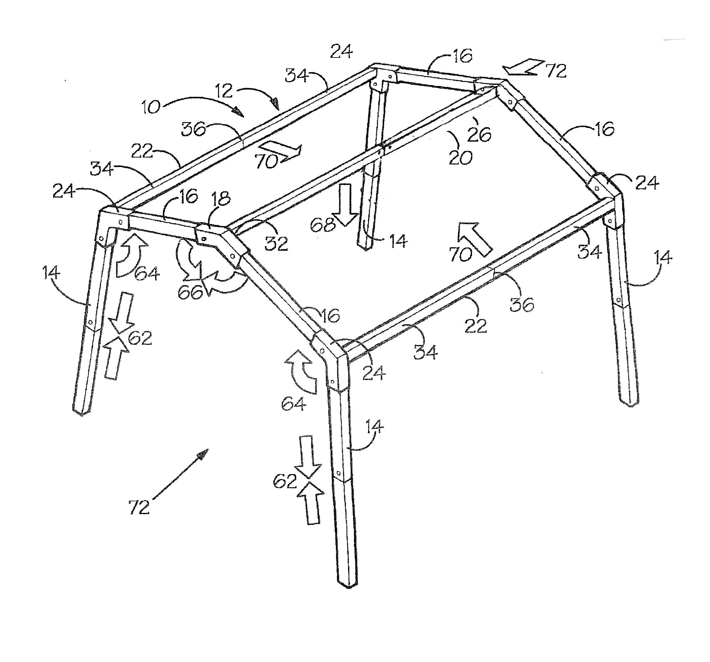
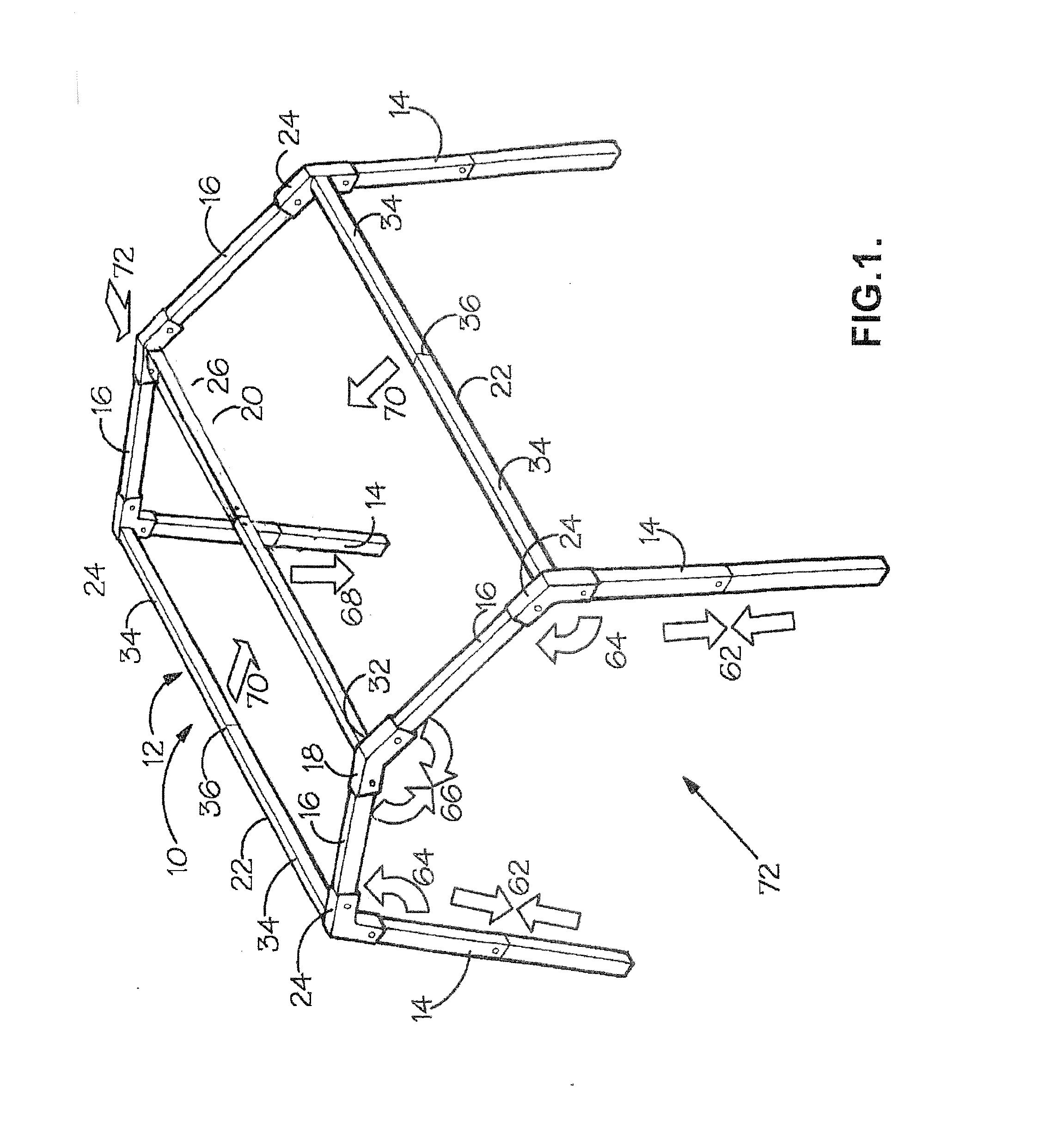
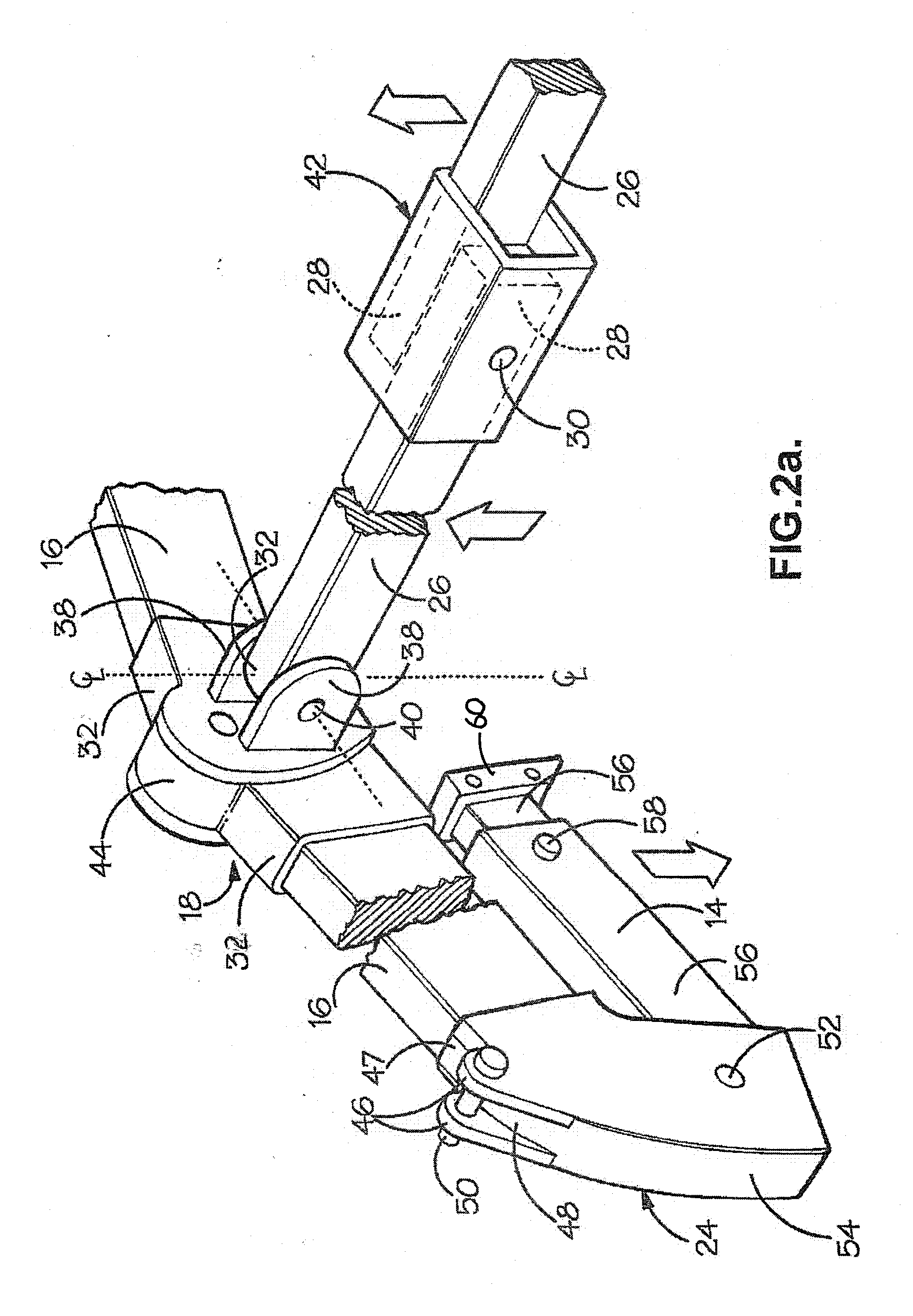
[0039]In FIG. 1, a support frame 10 for a tent comprises a roof 12 supported off the ground by four splayed legs 14. The roof 12 and legs 14 are manufactured from various lengths of generally rectangular-section aluminium tubing which are connected to one another at their ends using hinges or connectors, which shall be described in detail below.

[0040]The roof 12 comprises a pair of spaced-apart and parallel gables each gable comprising a pair of inclined rafters 16 which are hingedly connected to one another at their upper ends by an apex connector 18. The apex connector 18 and rafters 16 all lie substantially in a common piano, or parallel planes, hereinafter the plane of the gable. The gables are connected to one another by: a ridge beam 20, which extends perpendicularly outwardly from, and which spans the distance between the apex connectors 18; and by a pair of parallel eaves beams 22 which extend perpendicularly outwardly from, and which span the distance between two leg connec...


PUM


Abstract

A support frame for a tent comprising a pair of spaced-apart gables each gable comprising a pair of rafters hingedly connected relative to one another at their upper ends via an apex connector to form an apex, and a ridge beam connected at its opposite ends to the apexes and pivotally moveable relative to each apex about a substantially fixed axis, the fixed axis lying in a plane that is substantially parallel to a plane containing the longitudinal axis of a rafter.

Description

BACKGROUND OF THE INVENTION[0001]This invention relates to tents, support frames for tents and in particular, but without limitation, to tents having external support frames.[0002]Tents are particularly suitable for use as temporary structures in a variety of situations because they can be collapsed for ease of transport, positioned and erected on-site, and collapsed and taken away when no longer required. A drawback of known tents is the time and often knowledge / skill they take to erect correctly, which drawback is particularly relevant to large tents and marquees.[0003]Many known tents exist that attempt to address the above problems, including:[0004]Published European Patent Application No: EP0777022 describes a tent structure having a frame that can be folded-down when not in use. This document discloses a tent frame having hingedly interconnected beams arranged such that the rafters making up the gables of the tent frame can be inverted to lower the ridge beam, whereupon the ri...

Claims


Application Information

Patent Timeline
Patent Type & Authority Applications(United States)
IPC IPC(8): E04H15/46E04H15/48
CPCE04H15/48
Inventor WATSON, DAVIDMCPARTLAND, PETER
Owner NBC SERVICE
Why Eureka
Try Eureka