
Railroad crossing

a technology for crossings and rails, applied in the direction of traffic gates, ways, transportation and packaging, etc., can solve the problems of difficult stopping of speeding vehicles approaching these intersections, serious concerns about accidents at railway crossings, and accidents that continue to occur

Inactive Publication Date: 2013-08-01
QUEENSLAND RAIL LIMITED
View PDF9 Cites 10 Cited by
  • Summary
  • Abstract
  • Description
  • Claims
  • Application Information

AI Technical Summary

Benefits of technology

This patent describes a crossing that includes a roundabout, a speed arrestor bed, an upright wall, and an access road. The speed arrestor bed is used to slow down vehicles approaching the crossing from the curved approach. The upright wall with visible markings helps to detect the arrestor bed and cushion the vehicle upon impact. The arrestor bed also has a pit filled with loose aggregate. The brightly painted road interconnection connects the curved approach and the arrestor bed. The technical effects of this invention are improved safety and efficiency of the crossing.

Problems solved by technology

However, in spite of the existence of these warning devices, accidents at railway crossing remain a serious concern with many accidents continuing to occur because of a failure to notice or obey the warning devices.
It can be difficult for speeding vehicles approaching these intersections to stop suddenly without entering the crossing.
U.S. Pat. No. 1,571,166 discloses a railroad crossing in which the angled approach is advantageously less disruptive to general vehicle traffic flow than US 2008 / 0185482, although is less effective in encouraging a reduction in speed of the vehicle.

Method used


Image

  • Railroad crossing
  • Railroad crossing
  • Railroad crossing

Examples


Embodiment Construction

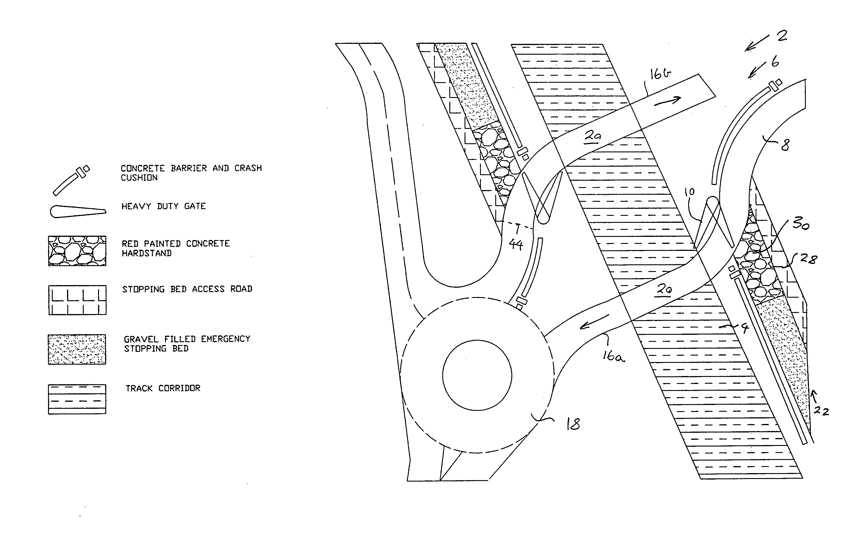
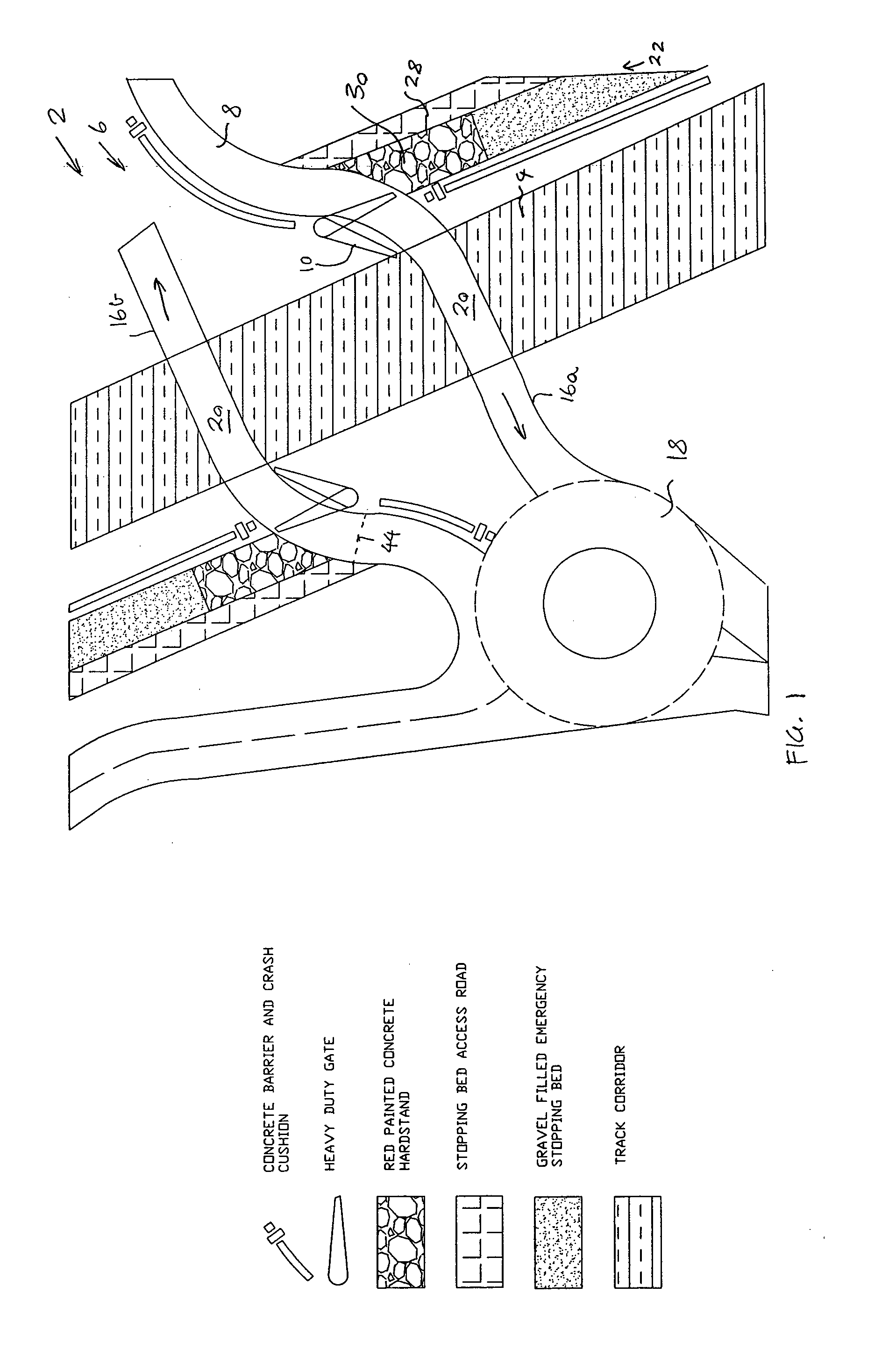
[0050]According to an embodiment of the present invention, there is provided a railroad crossing 2 as shown in FIG. 1. The railroad crossing 2 includes a railroad 4 along which a train can travel. The railroad crossing 2 further includes a road 6 crossing the railroad 4 and along which a vehicle or automobile can travel. The road 6 includes a curved approach 8 to the railroad 4. The curved approach 8 is effective in encouraging a reduction in speed of the vehicle by the driver without seriously disrupting vehicle traffic flow. The railroad crossing 2 further includes a movable vehicle impact barrier 10 which can sustain vehicle impact and prevent the vehicle from crossing the railroad 4. A detailed description of the railroad crossing 2 is provided below.

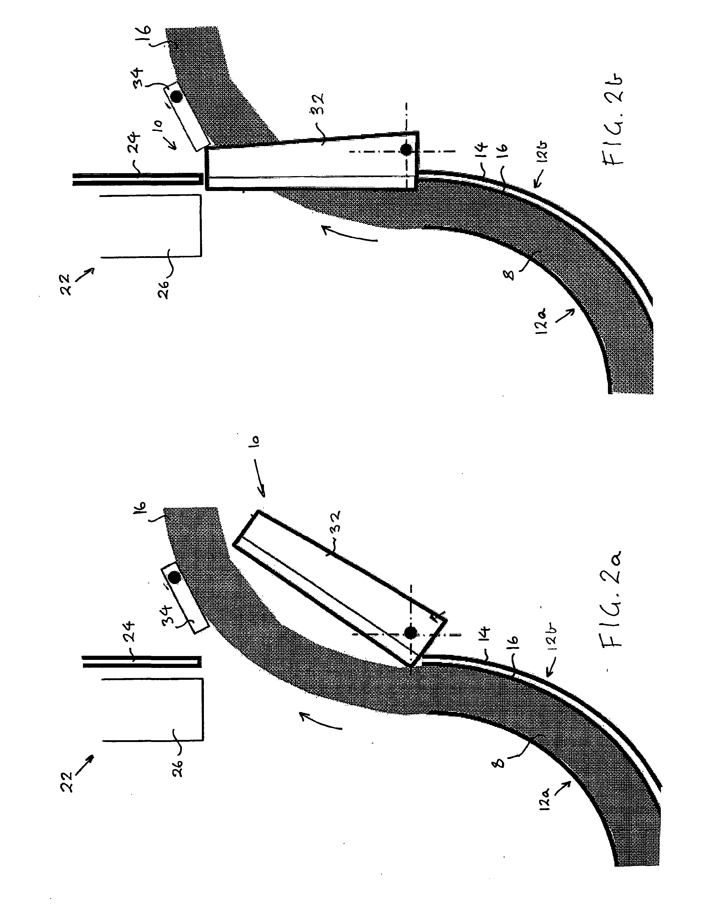
[0051]As can best be seen in FIG. 2, the approach 8 includes a pair of curved walls 12a, 12b through which a lane 16 of the road 6 passes. The outer wall 12b of the approach 8 includes visible markings to facilitate visual detection...


PUM


Abstract

The present invention relates to a railroad crossing (2). The railroad crossing (2) includes a railroad (4) along which a train can travel. The railroad crossing (2) further includes a road (6) extending across the railroad (4) and along which a vehicle or automobile can travel. The road (6) includes a curved approach (8) to the railroad (4). The curved approach (8) is effective in encouraging a reduction in speed of the vehicle without seriously disrupting vehicle traffic flow. The railroad crossing (2) further includes a movable vehicle impact barrier (10) which can prevent the vehicle from crossing the railroad (4). The road (6) may include two separated traffic lanes (16a, 16b) in which vehicles travel in opposite directions, and this separation of the lanes (16) deters the vehicle from being driven from one lane 16a and into the other lane (16b) in an attempt to circumvent the barrier (10).

Description

TECHNICAL FIELD[0001]The present invention generally relates to a railroad crossing.BACKGROUND[0002]The reference to any prior art in this specification is not, and should not be taken as an acknowledgement or any form of suggestion that the prior art forms part of the common general knowledge.[0003]A railroad crossing (also called a level crossing) is a crossing of a railroad by a road. Railroad crossings are often fitted with warning devices such as lights, bells and automatic boom gates to warn vehicles to give way to approaching trains. However, in spite of the existence of these warning devices, accidents at railway crossing remain a serious concern with many accidents continuing to occur because of a failure to notice or obey the warning devices. For example, vehicles are invariably driven around boom gates rather than waiting for them to be raised.[0004]Many railroad crossings include a railroad and road which intersect at right angles. It can be difficult for speeding vehicl...

Claims


Application Information

Patent Timeline
Patent Type & Authority Applications(United States)
IPC IPC(8): B61L29/04B61L29/24
CPCB61L29/00B61L29/026B61L29/24E01F13/06B61L29/04B61L29/28
Inventor BAINES, STEPHENMCMAH, DAVID
Owner QUEENSLAND RAIL LIMITED
Learn More