

Security device for a sliding door or sliding window assembly
- Summary
- Abstract
- Description
- Claims
- Application Information
AI Technical Summary
Benefits of technology
Problems solved by technology
Method used
Image

Examples
Embodiment Construction
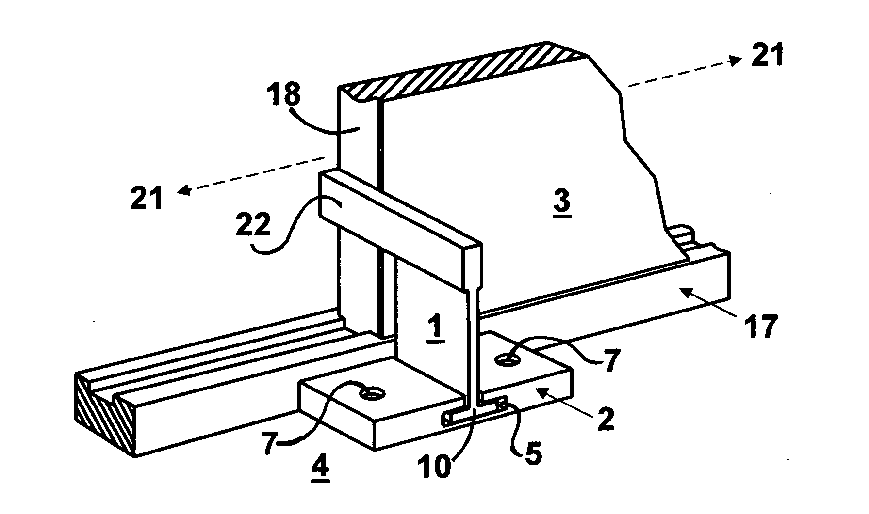
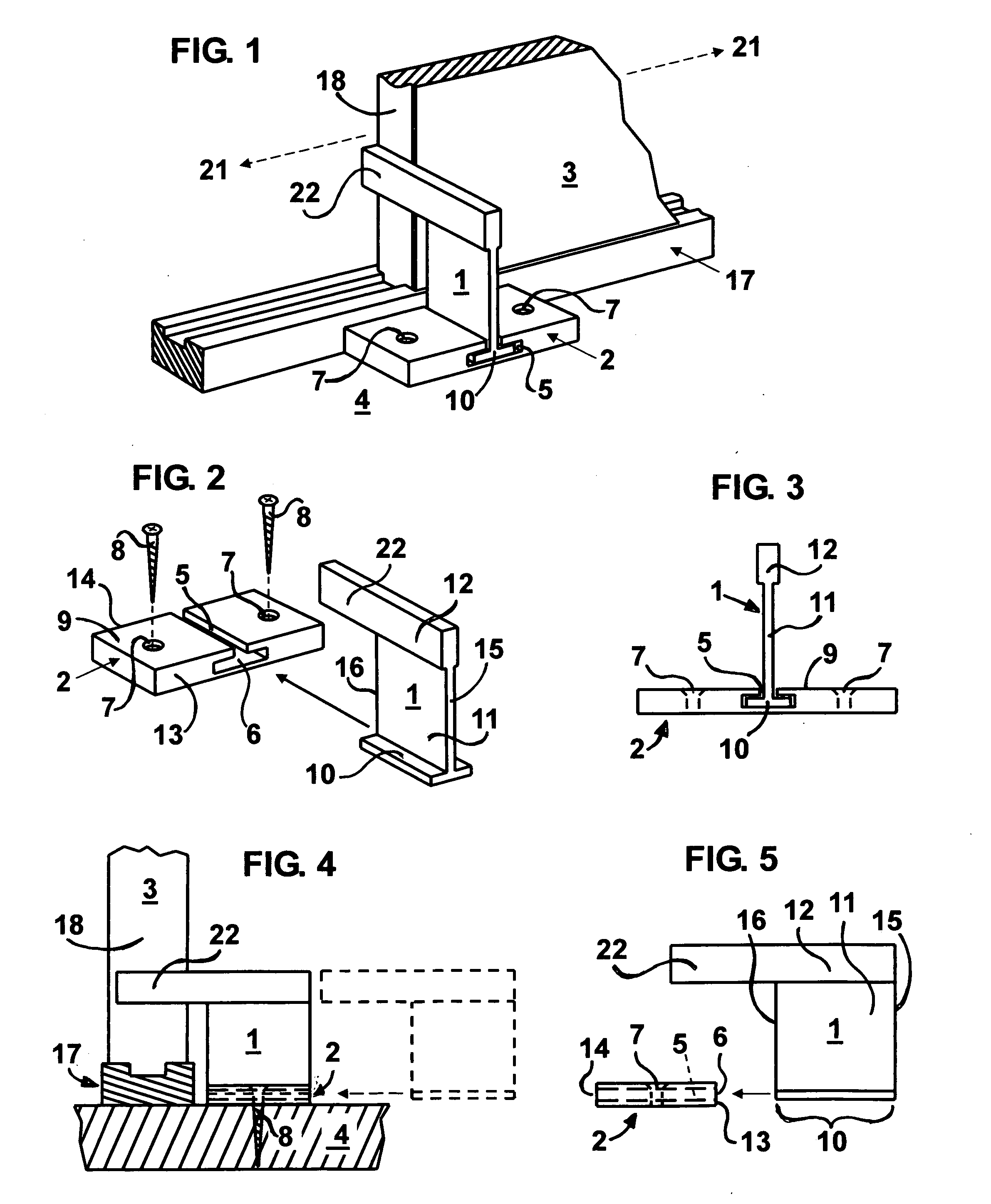
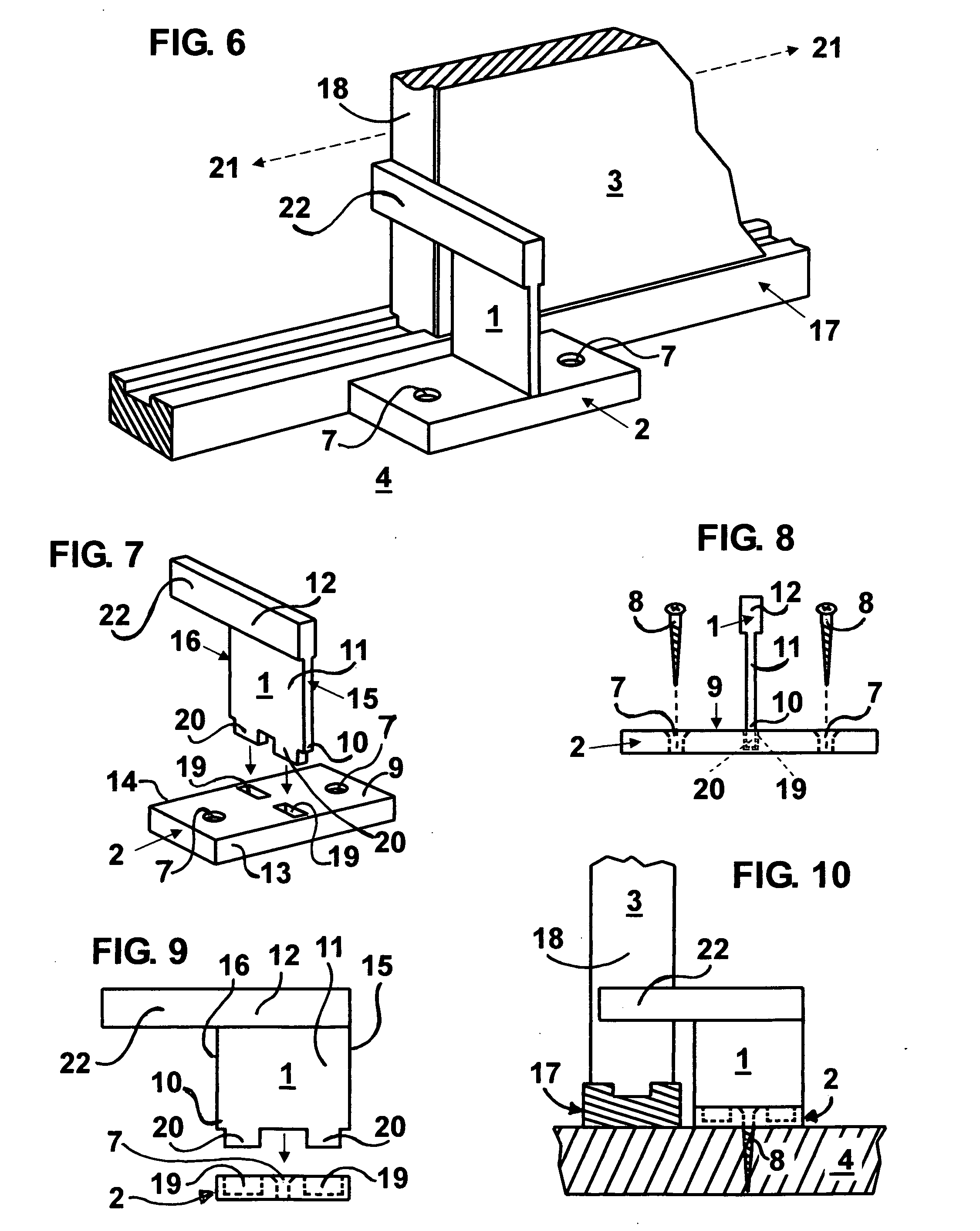
[0024]Referring to the drawings, FIGS. 1-10, of the present invention, wherein the same or generally similar features share common reference numerals. The numeral 3 indicates generally a sliding panel, of a sliding door or sliding window assembly, shown only partially and in the closed position, while the numeral 17 indicates generally the lower frame track of a sliding door or sliding window assembly, on or in which said sliding panel 3 moves horizontally back and forth, while the numeral 4 indicates generally the mounting surface to which the invention is affixed.
[0025]The sliding door and sliding window security devise shown in FIGS. 1-10 of the drawing sheets, consists of a removably interlocking stop member 1 and a base plate 2, each made of metal or other materials with good strength characteristics. While interlockingly engaged, in the in use position, as shown in FIG. 1 and FIG. 6, the removably interlocking stop member 1 will project into the path of movement 21 of the slid...
PUM
 Abstract
Description
Claims
Application Information