
Wireless communication device and communication terminal apparatus

a technology of communication terminal and wireless communication device, which is applied in the direction of electrically short antennas, antenna details, antennas, etc., can solve the problems of difficult to achieve desired results, and the difficulty of lowering the antenna correlation

Active Publication Date: 2013-08-01
SONY CORP
View PDF6 Cites 27 Cited by
  • Summary
  • Abstract
  • Description
  • Claims
  • Application Information

AI Technical Summary

Benefits of technology

This patent describes a wireless communication device with an improved antenna system that reduces interference and improves communication quality. The device includes a first antenna and a second antenna, which is a slit antenna. The slit antenna has a first conductive plate and a second conductive plate that are electrically short-circuited, which reduces the correlation between the two antennas. This allows for improved communication quality, even when multiple antennas are used. The patent also describes various ways to design and implement the antenna system. Overall, the patent provides a technical solution for improving wireless communication quality.

Problems solved by technology

In a service in the 700-MHz band in the U.S.A, for example, it is extremely difficult to lower the antenna correlation.
Accordingly, even if an attempt is made to improve correlation by changing the design of one antenna to change its directivity, a desired result cannot be easily obtained.

Method used


Image

  • Wireless communication device and communication terminal apparatus
  • Wireless communication device and communication terminal apparatus
  • Wireless communication device and communication terminal apparatus

Examples


Embodiment Construction

[0045]An embodiment of the present invention will be described in detail with reference to the drawings.

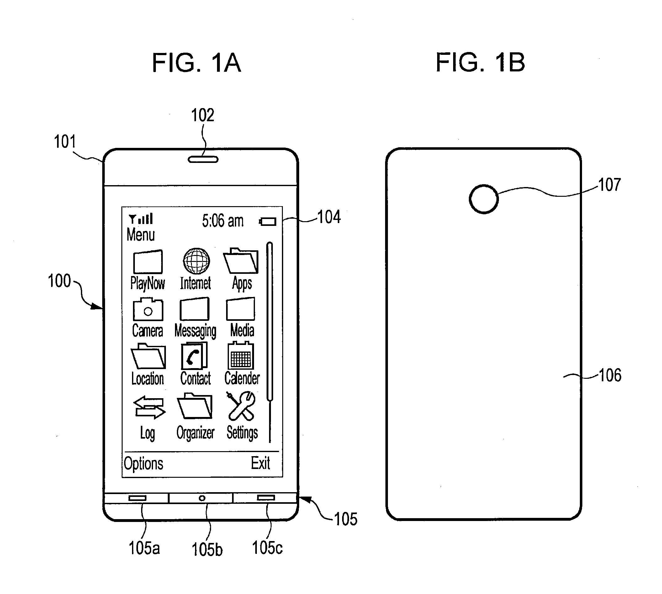
[0046]FIGS. 1(a) and 1(b) respectively illustrate the appearances of the front surface and rear surface of a mobile terminal called, for example, a smart phone as an example of a wireless communication device in this embodiment. This mobile terminal has a case 101, the outer shape of which is substantially a rectangular parallelepiped.

[0047]A display screen 104 of a display device such as, for example, an LCD is exposed on the front side of the mobile terminal illustrated in FIG. 1(a). A speaker part 102 is provided on the upper side of the display screen 104, and a manipulation part 105 including manipulation keys 105a to 105c is placed on the lower side of the display screen 104.

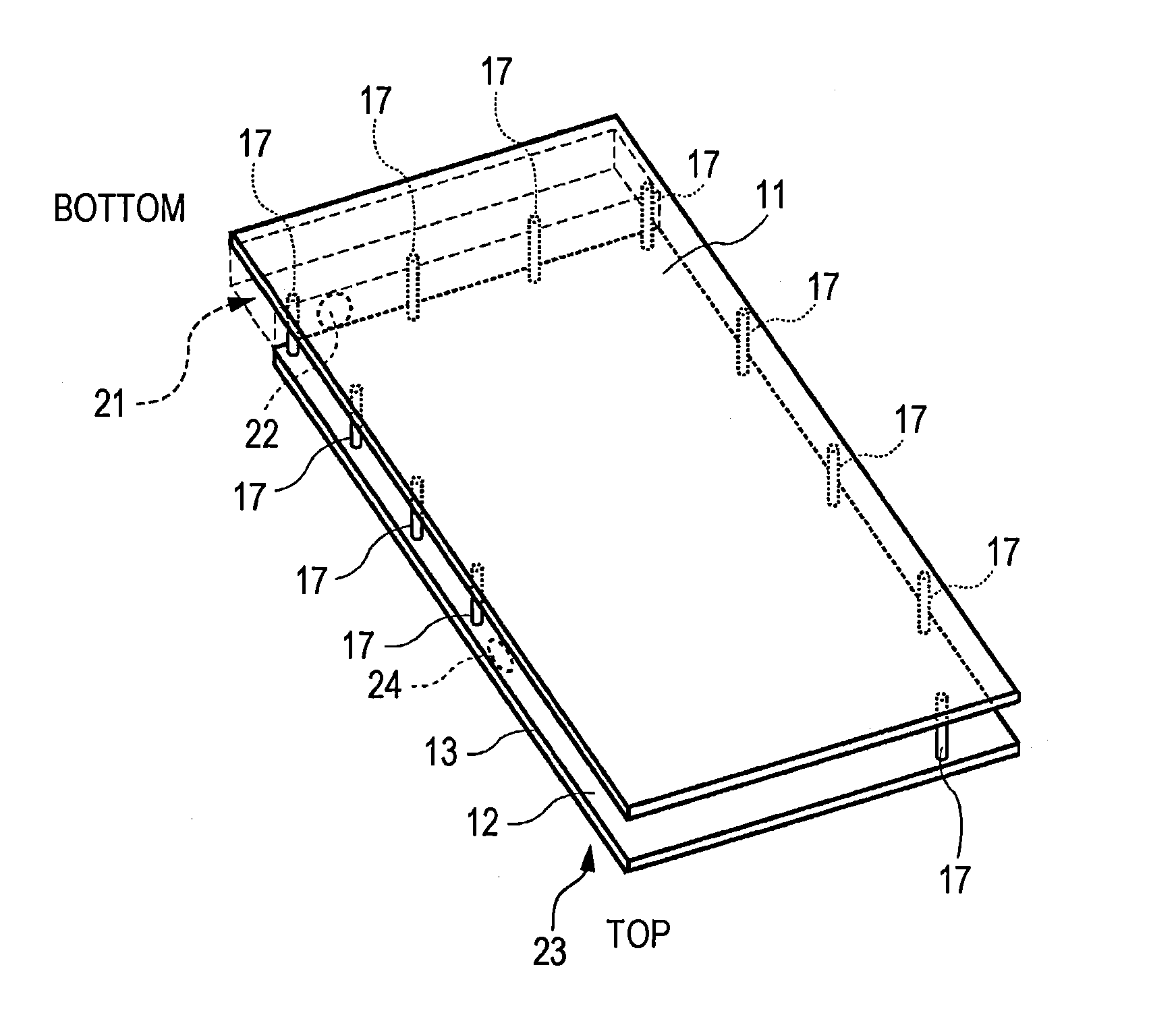
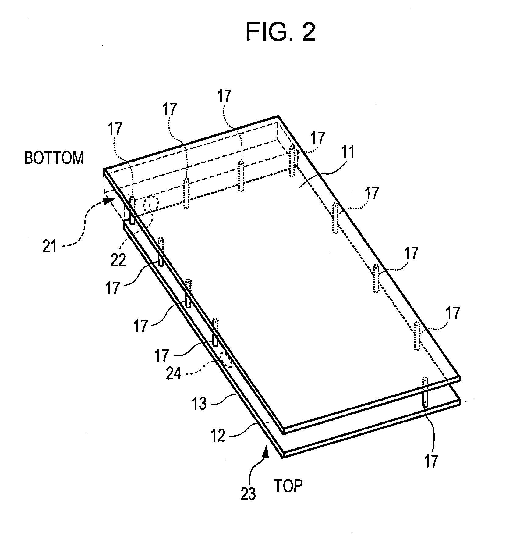
[0048]As well illustrated in FIG. 1(b), in this example, a conductive case panel 106 is placed on the entire rear surface of the mobile terminal. The case panel 106 forms a first conductive plate, which ...


PUM


Abstract

A communication terminal apparatus and wireless communication device include comprising a first antenna having a first feed point, and a second antenna including a slit antenna and having a second feed point, the second antenna being spaced apart from the first antenna. The slit antenna includes a first conductive plate, a second conductive plate disposed substantially parallel to the first conductive plate, and a short-circuiting structure electrically connected between the first conductive plate and the second conductive plate so as to electrically short the first conductive plate to the second conductive plate.

Description

CROSS REFERENCE TO RELATED APPLICATIONS[0001]The present application is based upon and claims the benefit of priority from U.S. Application No. 61 / 592,889, filed Jan. 31, 2012, the entire contents of which are incorporated herein by reference.TECHNICAL FIELD[0002]The present invention relates to a wireless communication device and communication terminal apparatus, such as a MIMO (multi-input multi-output) antenna device, that uses first and second antenna devices.BACKGROUND ART[0003]A service called long term evolution (LTE) is known as one of the high-speed data communication specifications for mobile telephones. From the technical viewpoint of the antenna, the LTE has the following features.[0004]That is, the LTE, which is a communication system called MIMO, achieves high-speed data communication by using a plurality of antennas in transmission and reception. A wireless communication device such as a mobile terminal using MIMO usually employs two antennas. Ideally, it is required ...

Claims


Application Information

Patent Timeline
IPC IPC(8): H01Q21/28
CPCH01Q21/28H01Q1/243H01Q9/0442H01Q9/0435H01Q9/0421
Inventor BUNGO, AKIHIRO
Owner SONY CORP
Learn More