
Method for generating diffuse reflection light and device thereof

a technology of diffuse reflection and light, which is applied in the direction of semiconductor devices, lighting and heating apparatus, instruments, etc., can solve the problems of affecting the equivalent luminescent area cannot be adjusted, and the soft light device hinders the original function of original light sources, etc., to achieve good effect, large soft light area, and excellent lightness

Inactive Publication Date: 2013-08-01
LI BING
View PDF18 Cites 3 Cited by
  • Summary
  • Abstract
  • Description
  • Claims
  • Application Information

AI Technical Summary

Benefits of technology

The present invention provides a method for generating diffuse reflection light that is easy to install and disassemble, with a soft light effect and adjustable equivalent luminescent area. It is also suitable for frequent movement. The technical effects include improved safety and convenience compared to previous methods, as well as better performance and flexibility for applications that require diffuse reflection light. A device based on this method is also provided for easy use.

Problems solved by technology

The disadvantages include: the installation and the disassembly are quite troublesome; the use in the open air or under the situation of frequent movement is time-consuming and laborious; certain skill is especially required for installation of a soft light box; the entire device is heavy, difficult for handholding and very inconvenient in movement; therefore, conventional devices are suitable for indoor use and use at a fixed position; they are extremely inconvenient when being used in open air.
The disadvantages include: small area of the light reflection and soft light material, which is within the same order of magnitude as the luminescent area of the light source and which, fundamentally, still belongs to point light source, and inferior soft light effect.
Some portable soft light devices hinder the original function of original light source from effecting during the installation and use thereof.
In addition, because the reflector of light box, and soft light and light reflection device in the prior art is fixed when being used and does not lead to area change, the equivalent luminescent area thereof cannot be adjusted.

Method used


Image

  • Method for generating diffuse reflection light and device thereof
  • Method for generating diffuse reflection light and device thereof
  • Method for generating diffuse reflection light and device thereof

Examples


Embodiment Construction

[0083]Further detailed description is made below with reference to the preferred embodiments shown in the drawings.

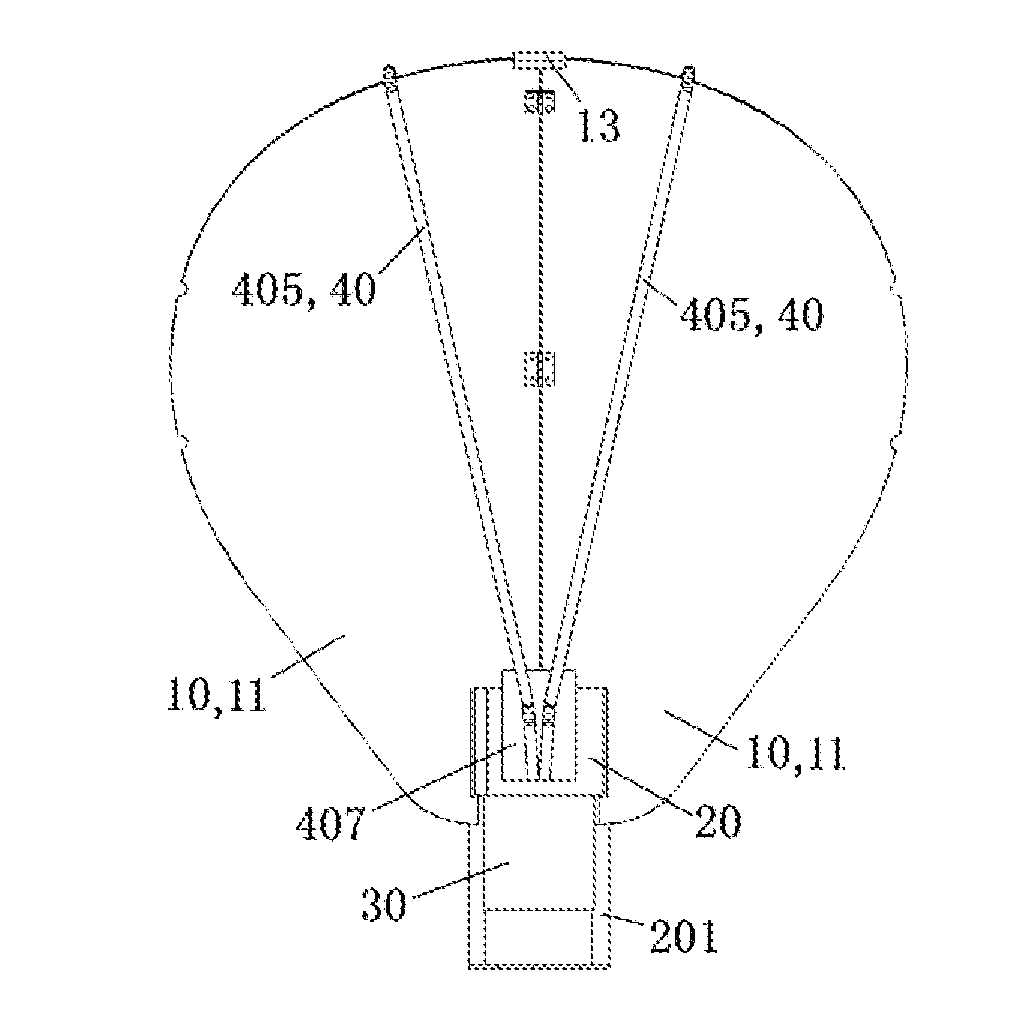
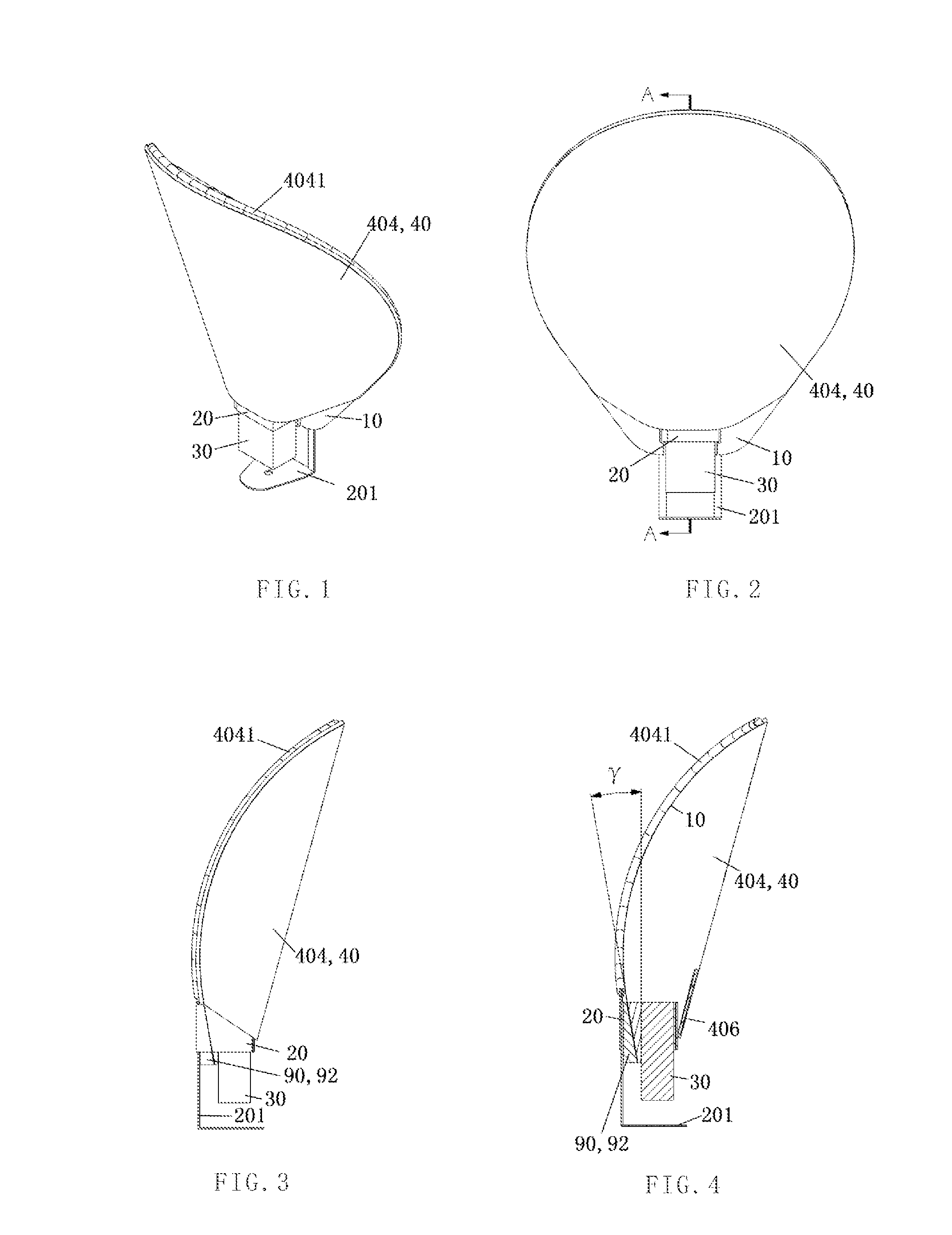
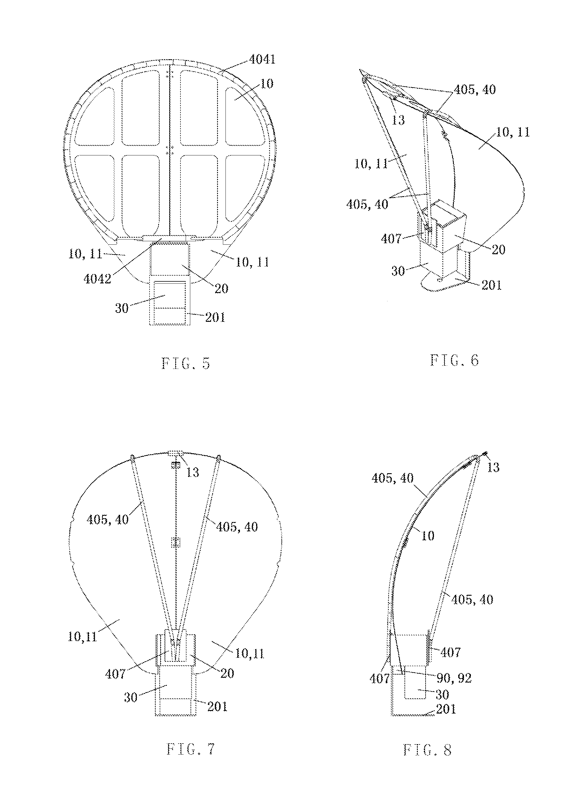
[0084]As shown in FIG. 1 to FIG. 37, the method in accordance with preferred embodiments of the present invention for generating diffuse reflection light is based on a luminescent lamp and comprises the following steps:

[0085]A. a reflector 10 is detachably fixed on the luminescent lamp 30 by means of a connector 20; and

[0086]B. the reflector 10 is elastically bent forwards by means of a pulling device 40 in order to focus the diffuse reflection light.

[0087]Also, in step B, the reflector 10 is elastically bent forwards in a longitudinal direction or a transverse direction by means of the pulling device 40, in order to obtain the diffuse reflection light.

[0088]There are two ways to use the reflector 10.

[0089]In accordance with the first way, the reflector is a solid plate. When the reflector is the solid plate, the surface of the reflector is provided with plenty of rugge...


PUM


Abstract

A method for generating diffuse reflection light and a diffuse reflection lamp are provided. The diffuse reflection lamp comprises a reflective plate (10), a connector (20) and a dragging device (40). The reflective plate (10) is removably fixed on the lamp by the connector (20) to reflect the light from the lamp. One end of the dragging device (40) is connected with the reflective plate (10), and the other end is connected with the connector (20); or the dragging device (40) hoops around the outer edge of the reflective plate (10). Therefore, the reflective plate (10) is elastically bended toward and formed into a curved arc surface to collect the diffuse reflection light.

Description

TECHNICAL FIELD[0001]The present invention relates to an illumination device, especially to a convenient method and a device for generating diffuse reflection light.BACKGROUND ART[0002]Light box, light reflection device, and soft light device are often needed in the process of photographing, and in particular in art photographing where the soft light effect is closely associated with the soft light area of the soft light device. The larger the soft light area is, the better the soft light effect is. The types of the soft light device in the prior art and their advantages and disadvantages are as follows:[0003]1. Conventional Light Box, Soft Light Box, Soft Light Umbrella, and Light Reflecting Umbrella:[0004]The advantages include: quite large area of light reflection and soft light material, which is 1 to 3 order of magnitudes larger than the luminescent area of original light source; and excellent soft light effect. The disadvantages include: the installation and the disassembly ar...

Claims


Application Information

Patent Timeline
Patent Type & Authority Applications(United States)
IPC IPC(8): F21V14/04
CPCF21V7/16F21V14/04F21Y2101/02G03B15/02G03B2215/0589F21V14/06G03B2215/0525G03B2215/0528G03B2215/0582G03B2215/0585F21V14/00F21Y2115/10
Inventor LI, BING
Owner LI BING
Learn More