Buffer structure of treadmill

a buffer structure and treadmill technology, applied in the field of buffer structure of treadmills, can solve the problems of troublesome operation, affecting the stability of the treadmill, and affecting the smoothness of the slide, so as to achieve the effect of simple adjustment and reduce the limitation of arrangemen

Inactive Publication Date: 2013-08-01
CHANG HUANG TUNG
View PDF10 Cites 26 Cited by
  • Summary
  • Abstract
  • Description
  • Claims
  • Application Information

AI Technical Summary

Benefits of technology

[0012]Both sides of the treadmill have the hand wheels for directional option when the treadmill is against the wall. The user can s...

Problems solved by technology

The operation is troublesome and takes a lot of time.
By the gear whe...

Method used


Image

  • Buffer structure of treadmill
  • Buffer structure of treadmill
  • Buffer structure of treadmill

Examples


first embodiment

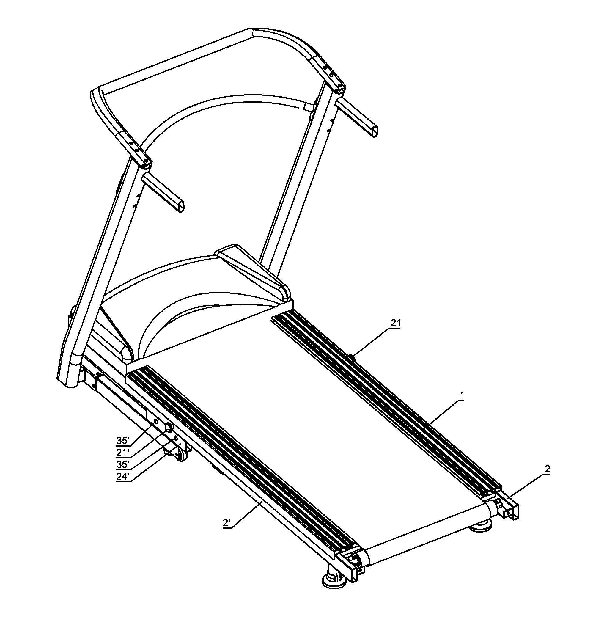
[0029]FIG. 2 through FIG. 5 and FIG. 3-A show the present invention. The link rod 23 to connect the hand wheels 21, 21′ and the gear wheels 22, 22′ penetrates the central sections of the two side rods 2, 2′. The two tooth racks 3, 3′ are coupled to the inner sides of the fixing rods 24, 24′ through the slide bolts 35, 35′, with the toothed portions 31, 31′ to mesh with the gear wheel 22, 22′. The buffer members 111, 111′ lean against the upper ends of the hollow cylinders 34, 34′. When the user wants to adjust the buffer degree, he / she can still stand on the load board 1 and turn either of the hand wheels 21, 21′ by himself or another person. The link rod 23 and the two gear wheels 22, 22′ are driven together to mesh with the two tooth portions 31, 31 so that the two tooth racks 3, 3 are slid through the two slots 34, 34′. Through the sleeves 353, 353′ on the slide bolts 35, 35′, the tooth racks 3, 3′ can be slid smoothly. After adjustment, the hollow cylinders 34, 34′ are moved to ...

third embodiment

[0031]FIG. 8 and FIG. 9 show the present invention. The present invention further comprises a motor 4 located at one end of the buffer unit 11, 11′ under either side of the load board 1 close to the gear wheel 22, 22′ of the corresponding side rod 2, 2′. The motor 4 comprises a transmission gear wheel 41 to mesh with the gear wheels 22, 22′. When the motor 4 is driven, the transmission gear wheel 41 will mesh with the gear wheel 22 at one side to move the tooth rack 3. Through the link rods 23, 36, the gear wheel 22′ and the tooth rack 3′ are linked to activate for adjusting the two hollow cylinders 33, 33′ to be under the desired buffer members 111, 111′, providing an electric adjustment and control.


PUM


Abstract

A buffer structure of a treadmill includes a load board, two side rods and two tooth racks. The two side rods includes a pair of hand wheels and a pair of gear wheels which are respectively located central sections of the two side rods and connected by a link rod, and a pair of fixing rods disposed under the link rod. The two tooth racks includes toothed portions at upper ends thereof to mesh with the gear wheels, fixing posts at inner sides thereof for insertion of the hollow cylinders, fixing bolts screwed to the fixing posts, and two slots at two sides of the fixing bolts. The two slide bolts are inserted through two through holes of the two side rods and the two slots and connected with nuts and washers. A gap is formed between the tooth racks and the side rods for slide.

Description

BACKGROUND OF THE INVENTION[0001]1. Field of the Invention[0002]The present invention relates to a buffer structure of a treadmill.[0003]2. Description of the Prior Art[0004]As shown in FIG. 1 and FIG. 1-A, Taiwanese Utility Model Patent No. M388948 discloses a conventional treadmill having a buffer mechanism. The treadmill comprises a load board 5 and two opposing supports 6. The buffer mechanism comprises buffer units 51 and a shaft 62. The buffer units 51 are disposed on the load board 5. The shaft 62 is connected between guide holds 61 of the two supports 6. The load boards 5 lean against the shaft 62 through the buffer units 51 to be suspended on the two supports 6. The buffer units 51 comprise a plurality of buffer members 511 which have different coefficients of elasticity. The shaft 62 can be rotated on the two supports 6 and moved relative to the buffer members 511 to lean against one of the buffer members 511.[0005]Two ends of the shaft 62 are provided with shaft sleeves 6...

Claims


Application Information

Patent Timeline
IPC IPC(8): A63B22/02
CPCA63B22/02A63B2022/0228A63B2022/0214A63B22/0214A63B22/0228
Inventor CHANG, HUANG-TUNG
Owner CHANG HUANG TUNG
Why Eureka
Try Eureka