

Method and device for image encoding/decoding using block split prediction
a video encoding and decoding technology, applied in the direction of signal generators with optical-mechanical scanning, color televisions with bandwidth reduction, signal generators, etc., can solve the problems of deteriorating prediction efficiency, reducing the accuracy of a split direction, and limited performance, so as to improve video data compression performance and improve image quality. the effect of restoring image quality
- Summary
- Abstract
- Description
- Claims
- Application Information
AI Technical Summary
Benefits of technology
Problems solved by technology
Method used
Image

Examples
first embodiment
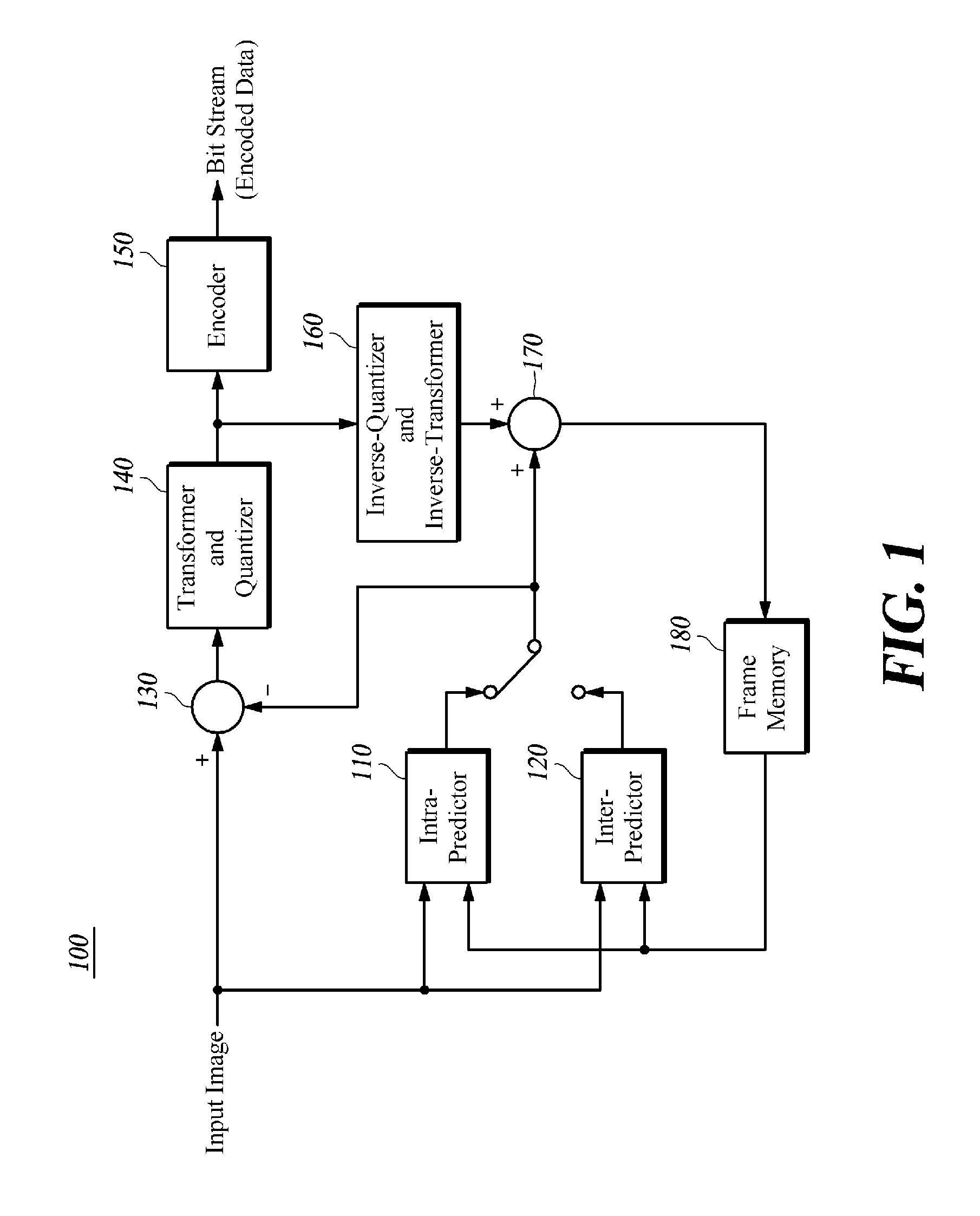
[0049]the inter-predictor 120 generates split candidates by splitting a current block using a set of one or more lines connecting points on two sides of the current block, generates candidate blocks by performing prediction for each partition of the current block split by one or more lines with respect to each split candidate, and selects, as a predicted block, a candidate block having pixel values most similar to the current block from among the generated candidate blocks.
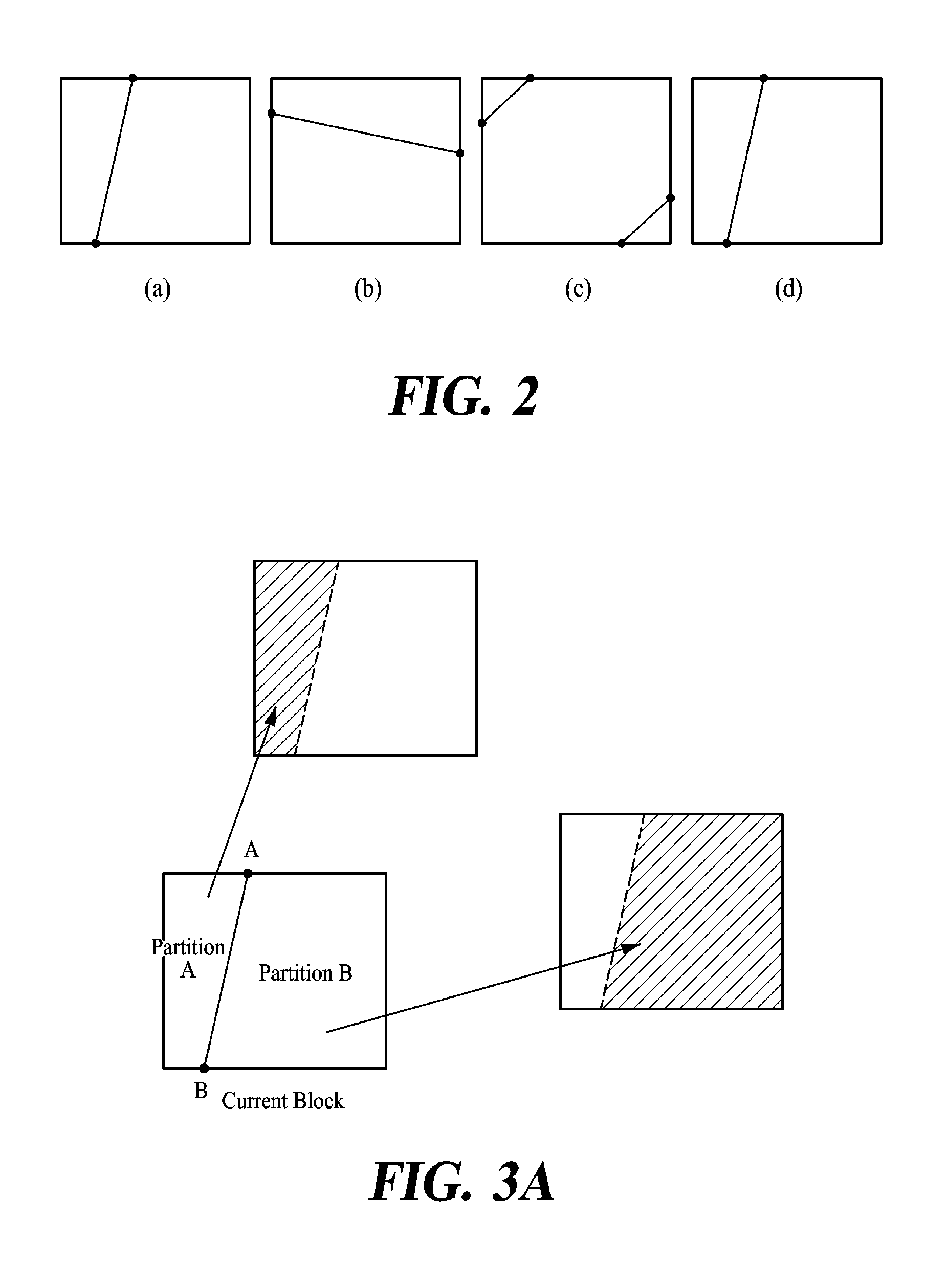
[0050]In this example, as illustrated in FIG. 2 at (a) to (d), a method that splits the current block in the inter-predictor 120 may split the current block into two parts using a single line as shown in FIGS. 2(a) and (b), and may split the current block into three parts using two lines as shown in FIGS. 2(c) and (d).
[0051]The inter-predictor 120 may generate candidate blocks by performing prediction for each partition with respect to each of the split candidates of FIG. 2 at (a) through (d).
[0052]FIGS. 3A and 3B...
second embodiment
[0059]the inter-predictor 120 extracts a predetermined number of feature points from a current block, selects a matching block having a distribution of feature points similar to a distribution of the extracted feature points, and performs prediction by setting the selected matching block to be a predicted block.
[0060]In this example, the encoder 150 may encode the information associated with feature points, and may transmit the encoded information to a decoding apparatus. In this example, the information associated with the feature points may correspond to location information associated with the feature points, that is, coordinates information associated with the feature points as illustrated in FIG. 4.
[0061]The encoder 150 may use, as the information associated with the feature points, a coefficient of a function that has the smallest error or variation from a set of lines connecting the feature points, as opposed to encoding the location information associated with the feature po...
third embodiment
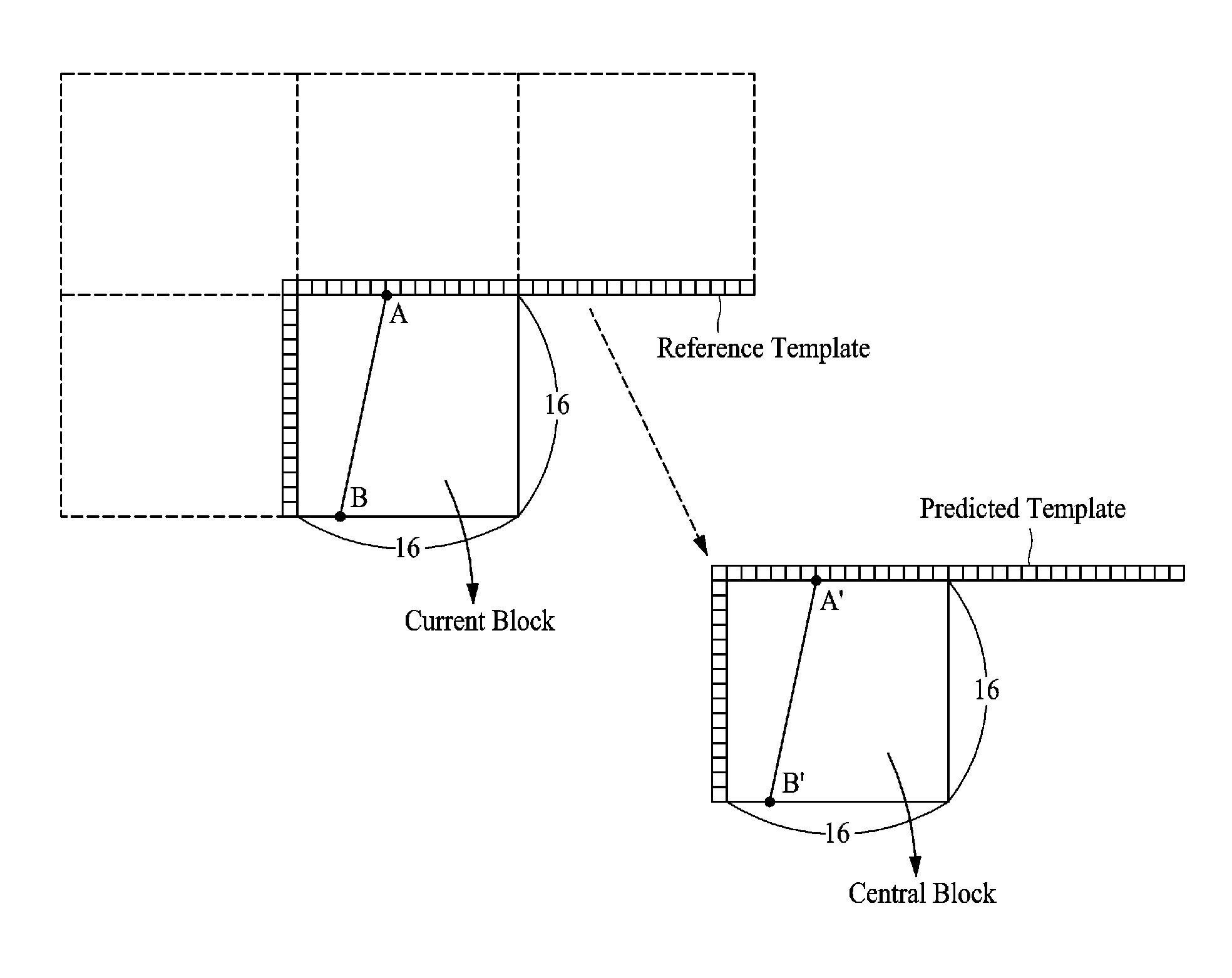
[0066]the inter-predictor 120 generates a predicted motion vector from a motion vector of an adjacent block, extracts split information of a current block from a block referred to by the generated predicted motion vector, and generates a predicted block by predicting the current block based on the extracted split information.
[0067]As one of the methods of obtaining a predicted motion vector from a motion vector of an adjacent block in FIG. 5, a method that uses a median of motion vectors MV1, MV2, and MV3 of an adjacent block may be used. As illustrated in FIG. 5, when MV2 is selected as a predicted motion vector, the split information of the current block may be set to a line AB to be identical to split information (line A′B′) of a block referred to by MV2. In this example, prediction may be performed for each partition of the current block split by the line AB, as illustrated in FIG. 3A or 3B, so as to generate the predicted block.
[0068]Here, the split information of the current b...
PUM
 Abstract
Description
Claims
Application Information