Vortex control apparatus

Inactive Publication Date: 2013-08-15
BROWNLOW ANTHONY +1
View PDF10 Cites 7 Cited by
  • Summary
  • Abstract
  • Description
  • Claims
  • Application Information

AI Technical Summary

Benefits of technology

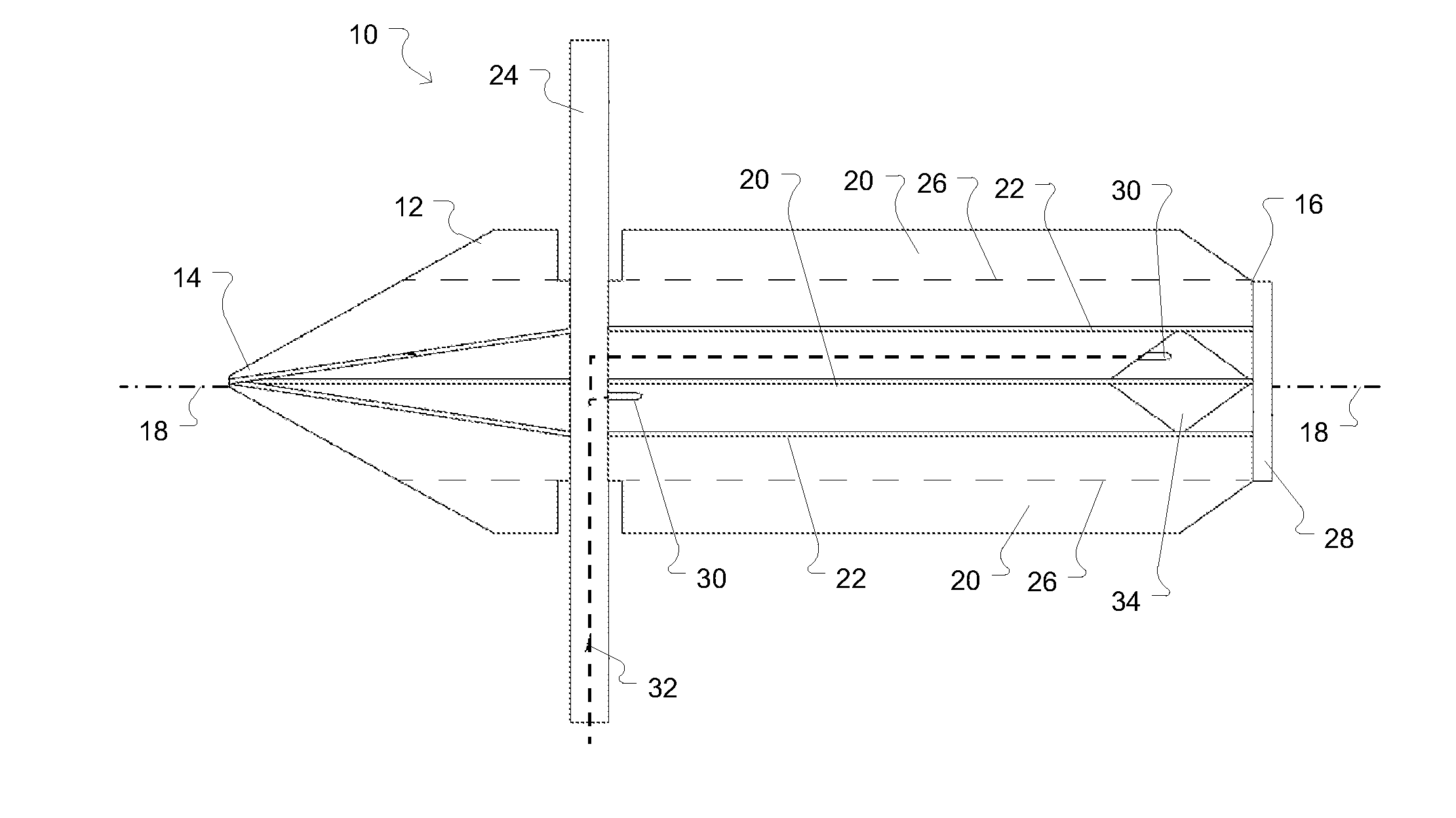
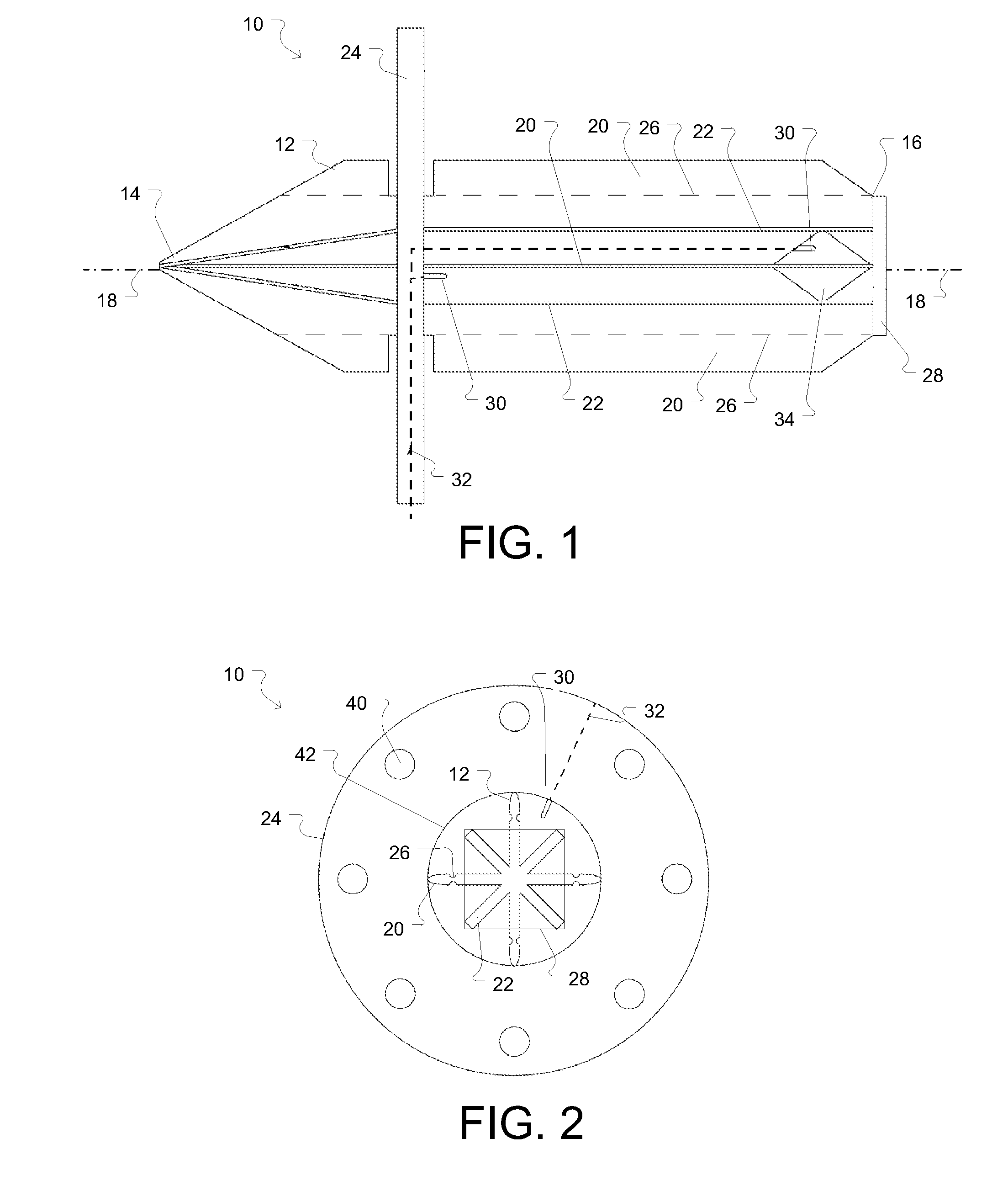
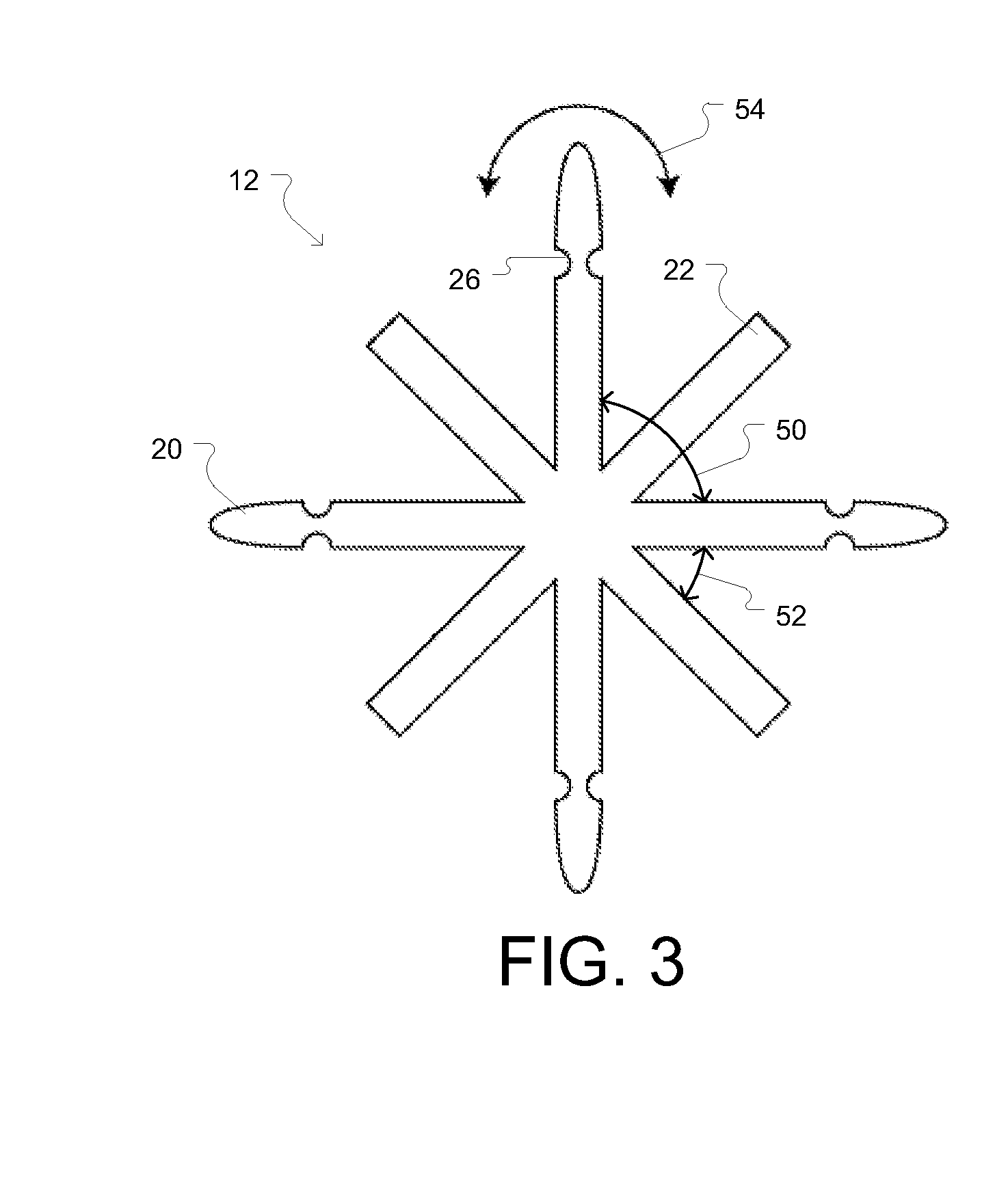
[0005]In light of the tendency for a vortex to occur in tanks, outlets, and pipes the present invention relates to a vortex control systems and apparatus that can reduce or eliminate the occurrence of vortices in liquid flowing into a pipe. In some aspects, the vortex control apparatus has a unit body extending longitudinally along a central axis. The unit body can have a plurality of primary fins extending radially from its central axis. Each of the plurality of primary fins can be equally spaced apart. The unit body can also have a plurality of secondary fins extending radially from its central axis. Each of the plurality of primary fins can be spaced equidistantly apart and be po

Problems solved by technology

This is undesirable as the hydrocarbons may be pollutants, rendering the more dense water unfit for certain types of

Method used


Image

  • Vortex control apparatus
  • Vortex control apparatus
  • Vortex control apparatus

Examples


Example

[0013]A description of embodiments of the present invention will now be given with reference to the Figures. It is expected that the present invention may be embodied in other specific forms without departing from its spirit or essential characteristics. The described embodiments are to be considered in all respects only as illustrative and not restrictive. The scope of the invention is, therefore, indicated by the appended claims rather than by the foregoing description. All changes that come within the meaning and range of equivalency of the claims are to be embraced within their scope.

[0014]For the purposes of the present invention, the phrase “A / B” means A or B. For the purposes of the present invention, the phrase “A and / or B” means “(A), (B), or (A and B).” For the purposes of the present invention, the phrase “at least one of A, B, and C” means “(A), (B), (C), (A and B), (A and C), (B and C), or (A, B and C).”

[0015]Various operations may be described as multiple discrete oper...


PUM


Abstract

A vortex control apparatus is disclosed which has a unit body extending longitudinally along a central axis. The unit body has a plurality of primary fins extending radially from its central axis. The unit body also has a plurality of secondary fins extending radially from its central axis. Each of the plurality of primary fins can be spaced apart and be positioned disposed between two primary fins. The vortex control apparatus can also include a flange coupled to the unit body that extending radially from the central axis of the unit body. The flange can also extend radially from the central axis of the unit body farther than primary fins or the secondary fins.

Description

BACKGROUND[0001]1. Field of the Invention[0002]This application relates generally to vortex control apparatuses. More specifically, this application relates to systems and apparatuses for reducing the likelihood of a vortex in liquids flowing in or into a pipe.[0003]2. Background of the Invention and Related Art[0004]In tanks holding liquids, a lighter liquid such as hydrocarbons separate from and sit on top of denser liquids such as water used to extract the hydrocarbons below. Usually an extraction port or valve sits near the bottom of such tanks and the lower liquid can be extracted via the extraction port or valve—sometimes by virtue of gravity but often using a mechanical vacuum or other pump to increase the speed of extraction. Whether under gravity or even more so under force of accelerated extraction, as the liquid is extracted from the tank, a vortex forms that allows top and bottom fluids to be pulled simultaneously form the tank. This is undesirable as the hydrocarbons ma...

Claims


Application Information

Patent Timeline
IPC IPC(8): F15C1/16
CPCF15D1/04Y10T137/2098
Inventor BROWNLOW, ANTHONYRICHARDSON, WILLIAM
Owner BROWNLOW ANTHONY
Why Eureka
Try Eureka