

Image forming apparatus
- Summary
- Abstract
- Description
- Claims
- Application Information
AI Technical Summary
Benefits of technology
Problems solved by technology
Method used
Image

Examples
first embodiment
[0028]Embodiments of the present invention are described below with reference to the accompanying drawings. Note that the following embodiments should not be construed as restricting the sprit or scope of the invention described in the attached claims in any way, and not all combinations of features described in the embodiments of the present invention are indispensable for solving means of the present invention.
Image Forming Operation Performed by Image Forming Apparatus
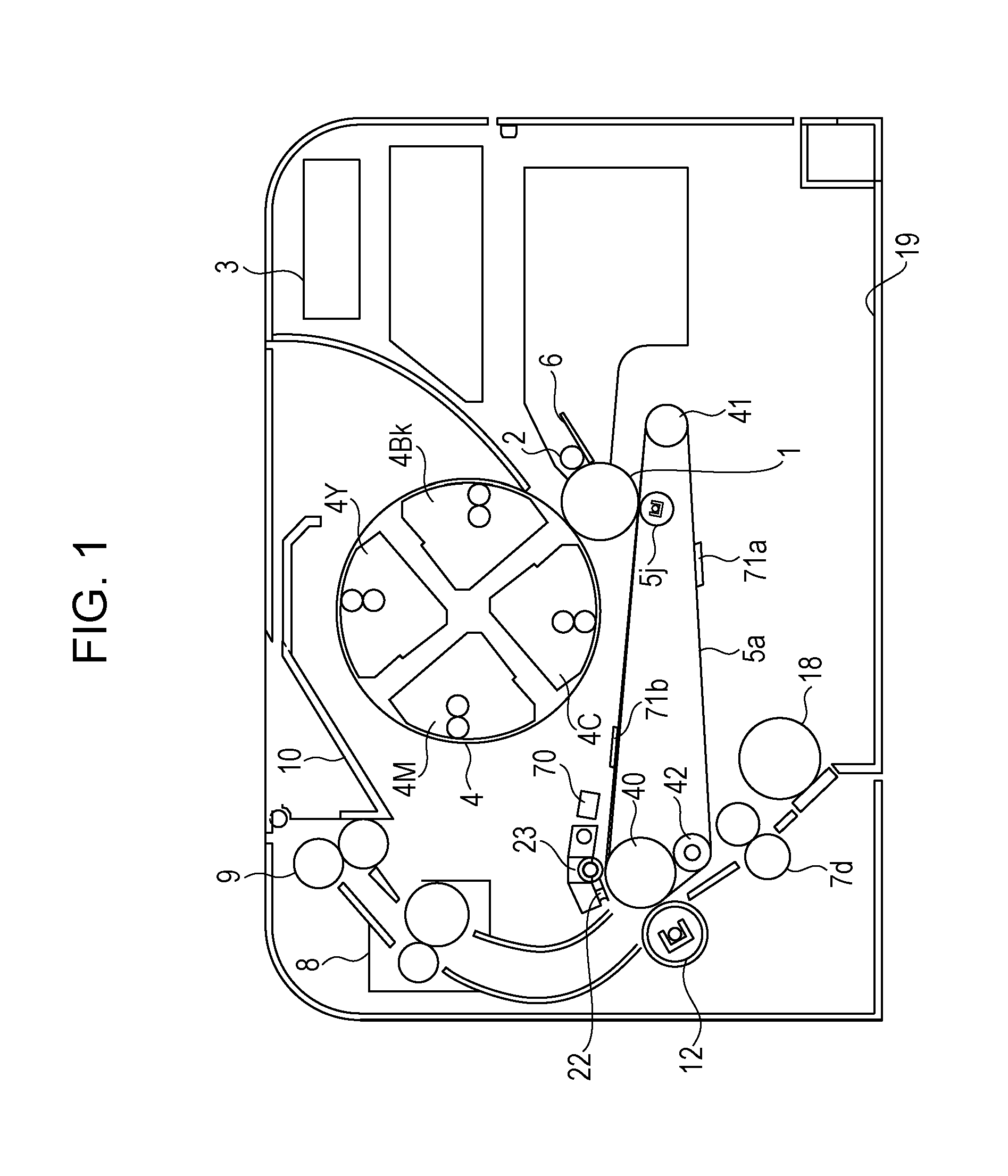
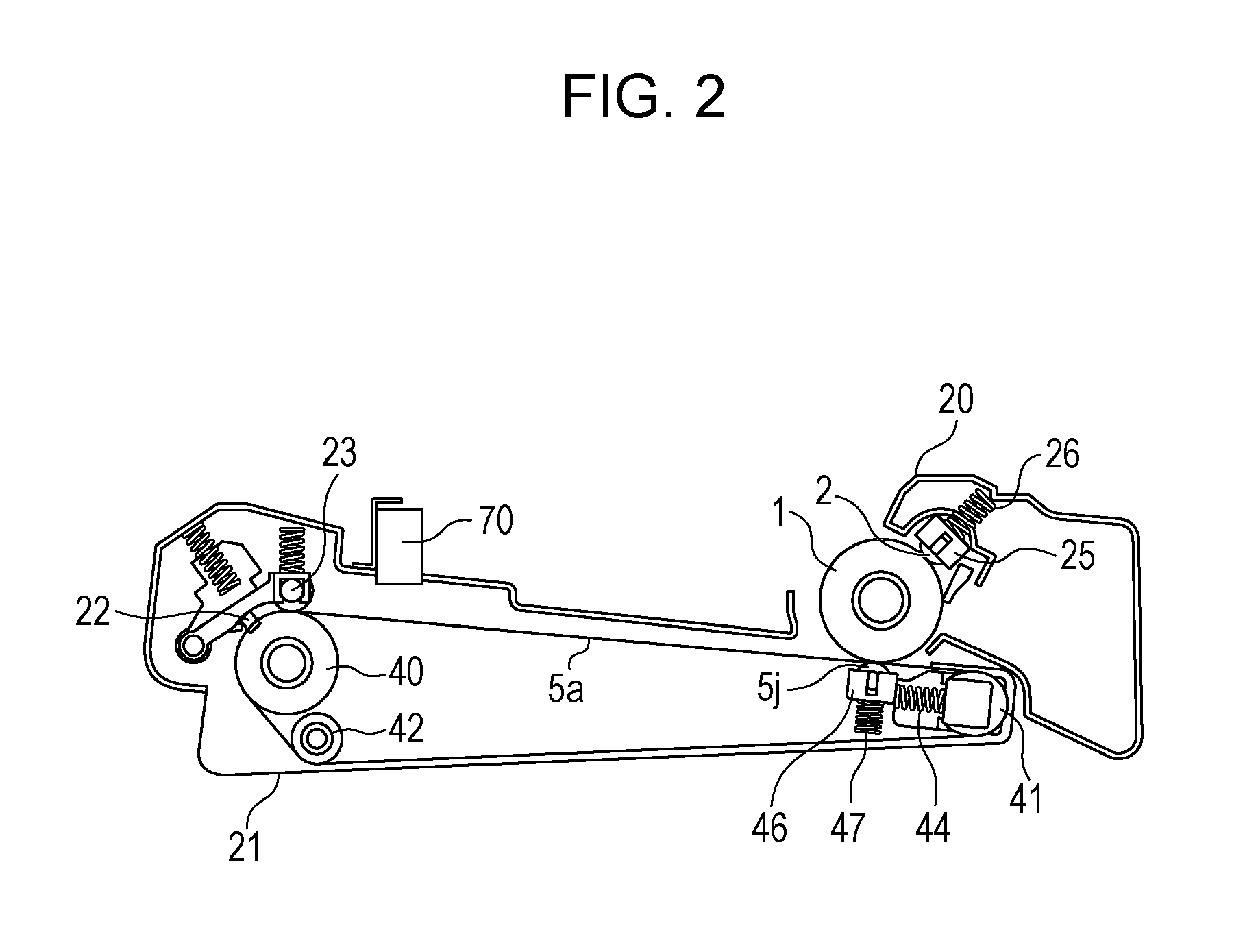
[0029]FIG. 1 is a schematic illustration of an exemplary configuration of a laser printer, which is an example of an image forming apparatus. The image forming operation performed by the image forming apparatus is described below. An intermediate transfer belt 5a serving as the intermediate transfer member is held tight around a driving roller 40, a first driven roller (a tension roller) 41, and a second driven roller (an idler roller) 42 serving as a tension member. The intermediate transfer belt 5a is rotated in s...
second embodiment
[0056]The first embodiment has been described with reference to a technique for forming an image so that a toner image does not overlap a wrinkle of the intermediate transfer belt 5a when an image of an A4 size is formed as an example. In a second embodiment, a control method is described for minimizing a negative impact of a wrinkle on a formed image even when a difference between the circumferential length of the intermediate transfer belt 5a and the size of the formed image is small and, unfortunately, a toner image is transferred onto a wrinkle of the intermediate transfer belt 5a. Note that since the configuration of an image forming apparatus and the structure of the intermediate transfer belt 5a are the same as those of the first embodiment, descriptions thereof are not repeated. For simplicity of description, description of the second embodiment is made with reference to formation of an image having a LEGAL size. However, the circumferential length of the intermediate transf...
third embodiment
[0066]The first and second embodiments have been described with reference to the techniques for forming an image with an optimum FPOT while reducing a negative impact of the wrinkle formed in the intermediate transfer belt 5a. According to the present embodiment, a technique for performing control so that a patch image formed when calibration is performed is not adversely affected by a wrinkle formed in the intermediate transfer belt 5a is described.
[0067]FIG. 16 illustrates a patch image used for calibration. An area 1801 includes a wrinkle onto which a toner image is not intended to be transferred, and a toner image is transferred into an area 1802. When calibration is performed and if a patch image is formed so as to overlap a wrinkle, a reflected light beam that generates noise may be detected by a color density sensor. Therefore, the detection accuracy may be decreased. Accordingly, a patch image is formed in the area 1802 to which a toner image is transferred without using the...
PUM
 Abstract
Description
Claims
Application Information