
Image capture system and method for synchronizing image

a technology of image capture and image synchronization, applied in the field of image control system, can solve problems such as time jump phenomenon, and achieve the effects of reducing or eliminating the occurrence of discontinuous timestamps, and expanding industrial applicability

Active Publication Date: 2018-10-09
VIVOTEK INC
View PDF18 Cites 0 Cited by
  • Summary
  • Abstract
  • Description
  • Claims
  • Application Information

AI Technical Summary

Benefits of technology

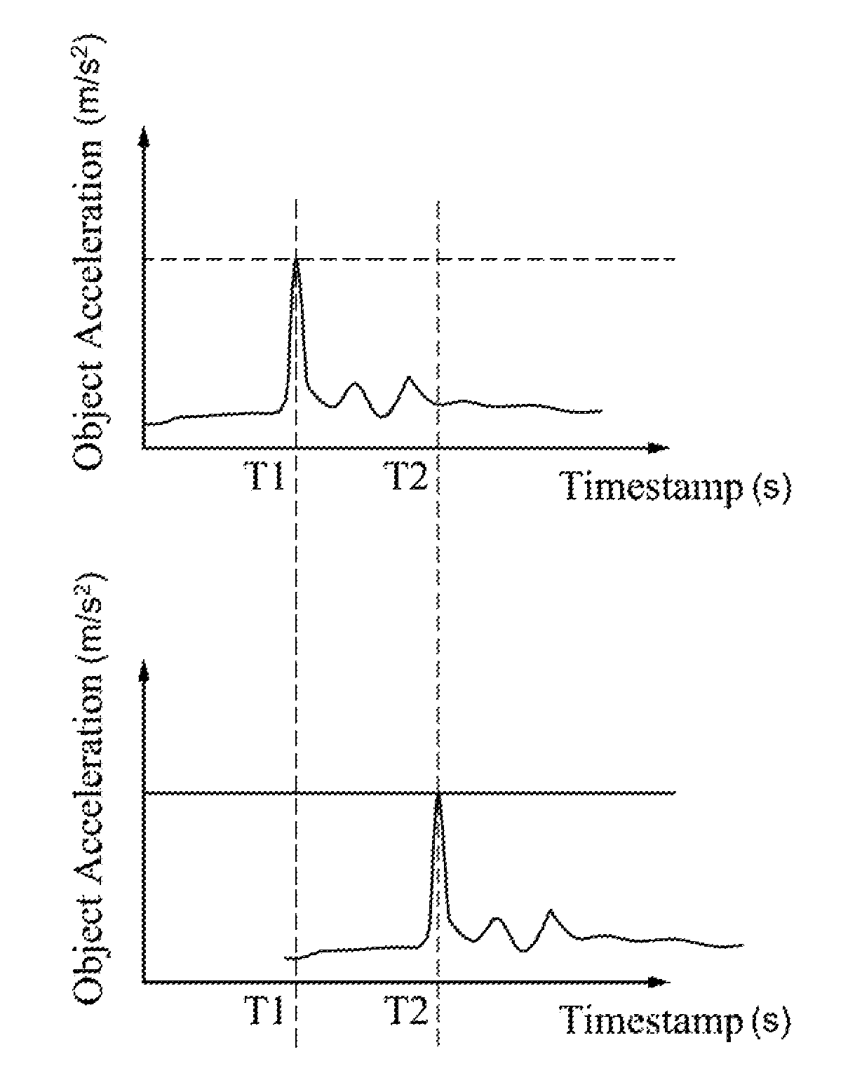
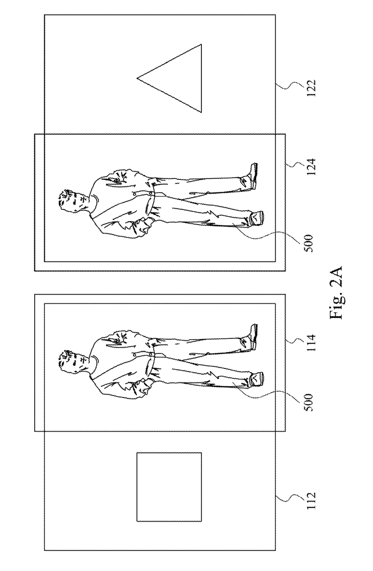
[0010]In summary, the technical solution of the present disclosure has obvious advantages and beneficial effects as compared with the prior art. Through the above technical solution, considerable advances in technology and extensive industrial applicability can be achieved. The processing device according to the present disclosure determines whether the captured images have the same object after receiving the image information captured by different image capture devices. If the captured images are determined to have the same object, the processing device tracks the object and modifies the timestamps of the captured images according to an event of the object that subsequently occurs. Therefore, as compared with the method in which all the image capture devices are connected through the Internet to synchronize the timestamps, not only can the image capture system according to the present disclosure effectively correct the time difference between the captured images, but the image capture system according to the present disclosure can also significantly reduce or eliminate the occurrence of discontinuous timestamps so as to maintain a high degree of synchronization between the captured images.

Problems solved by technology

However, when the time synchronization of the image capture device is performed, discontinuous timestamps between the images can possibly result, which in turn causes the time jump phenomenon.

Method used


Image

  • Image capture system and method for synchronizing image
  • Image capture system and method for synchronizing image
  • Image capture system and method for synchronizing image

Examples


Embodiment Construction

[0019]Reference will now be made in detail to embodiments of the present disclosure, examples of which are described herein and illustrated in the accompanying drawings. While the disclosure will be described in conjunction with embodiments, it will be understood that they are not intended to limit the disclosure to these embodiments. Description of the operation does not intend to limit the operation sequence. Any structures resulting from recombination of devices with equivalent effects are within the scope of the present disclosure. It is noted that, in accordance with the standard practice in the industry, the drawings are only used for understanding and are not drawn to scale. Hence, the drawings are not meant to limit the actual embodiments of the present disclosure. In fact, the dimensions of the various features may be arbitrarily increased or reduced for clarity of discussion. Wherever possible, the same reference numbers are used in the drawings and the description to refe...


PUM


Abstract

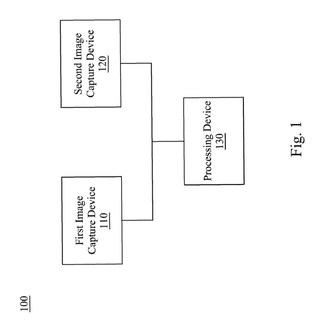
An image capture system includes a first image capture device, a second image capture device and a processing device, and the processing device is electrically connected to the first image capture device and the second image capture device. The first image capture device is configured to capture a first image, and the second image capture device is configured to capture a second image. The processing device is configured to receive first information transmitted from the first image capture device and second information transmitted from the second image capture device, and determines whether the first image and the second image have a same object based on the first information and the second information. If the processing device determines that the first image and the second image have the same object, the processing device synchronizes timestamps of the first image and the second image according to an event of the object.

Description

RELATED APPLICATIONS[0001]This application claims priority to Taiwan Application Serial Number 105111101, filed Apr. 8, 2016, which is herein incorporated by reference.BACKGROUND[0002]Field of Invention[0003]The present disclosure relates to an image control system. More particularly, the present disclosure relates to an image capture system and a method for synchronizing an image.[0004]Description of Related Art[0005]In order to achieve wide area surveillance in application scenarios, most of the currently adopted approaches are disposing multiple image capture devices in the application scenario so as to completely capture images in different areas of the application scenario. Since there may exist a timestamp difference between images captured by different image capture devices at the same time, time synchronization needs to be performed between the different image capture devices to correct the difference in the timestamp.[0006]Generally speaking, each of the image capture devic...

Claims


Application Information

Patent Timeline
Patent Type & Authority Patents(United States)
IPC IPC(8): H04N5/04G06T7/70H04N7/18G06T7/292H04N1/00G08B13/196
CPCH04N5/04G06T7/292G06T7/70H04N1/00114H04N7/181G08B13/196G06T2207/30196G06T2207/10016
Inventor LIU, CHENG-CHIEHCHANG, CHAO-MINGLIU, WEI-MING
Owner VIVOTEK INC
Learn More