Air spring for railroad car

a technology for air springs and railroad cars, which is applied in the direction of shock absorbers, mechanical devices, transportation and packaging, etc., can solve the problems of easy separation of the end of the elastic member in the elastic mechanism from the lower support, and achieve the effects of stable product quality, reduced or eliminated defects, and strong bonding

Inactive Publication Date: 2016-12-13
NITTA CHEM IND PROD CO LTD
View PDF22 Cites 0 Cited by
  • Summary
  • Abstract
  • Description
  • Claims
  • Application Information

AI Technical Summary

Benefits of technology

[0018]According to the invention described herein, as will be described in detail in the Embodiment section, an enlarged end is bonded to an annular groove in a wider area, so that there is no (or less) possibility that the adhesive applied in the annular groove will flow out of the annular groove with the in-flowing unvulcanized rubber during the forming. Therefore, a necessary and sufficient amount of adhesive is secured, so that the downward enlarged end and the annular groove, or the lower support, are firmly bonded together as intended. Since the bottom of the annular groove is formed as an annular tapered bottom that is inclined at an angle such that the height decreases radially outwards, no air pockets are formed when unvulcanized rubber is poured in during the molding, which provides the advantage of stable product quality. By thus reviewing the structure of the part where the elastic material and the lower support make contact with each other, the “bond separation” failures in which the lower end of the elastic material separates from the lower support are prevented or reduced, and so an air spring for railroad cars with an improvement to reduce or eliminate occurrence of defects can be provided.
[0019]According to the invention as described herein, no air bubbles remain in inner corners when the elastic material is poured in during the molding, and the contact area between an annular outer circumferential portion of the downward enlarged end and the annular bottom is increased, which additionally provides the advantage of a stronger bond by the adhesive. Namely, the effects by the invention according to claim 1 described above are enhanced.
[0020]In the present invention, described herein, the elastic member may have a generally barrel-shaped outer contour having a largest diameter in a middle part in a height direction, or as as described herein, the elastic member may be made of rubber that has excellent versatility and cost performance.

Problems solved by technology

As load conditions and the like for air springs for railroad cars are more and more stringent, a problem that the end of an elastic member in the elastic mechanism tends to easily separate from the lower support has emerged.
There is a problem wherein the detachment or separation of the lower end of the elastic member can readily occur from the outer periphery in any of the elastic mechanisms having these structures.
This problem occurs similarly with other elastic materials than rubber such as synthetic resin having elasticity.

Method used


Image

  • Air spring for railroad car
  • Air spring for railroad car
  • Air spring for railroad car

Examples


embodiment 1

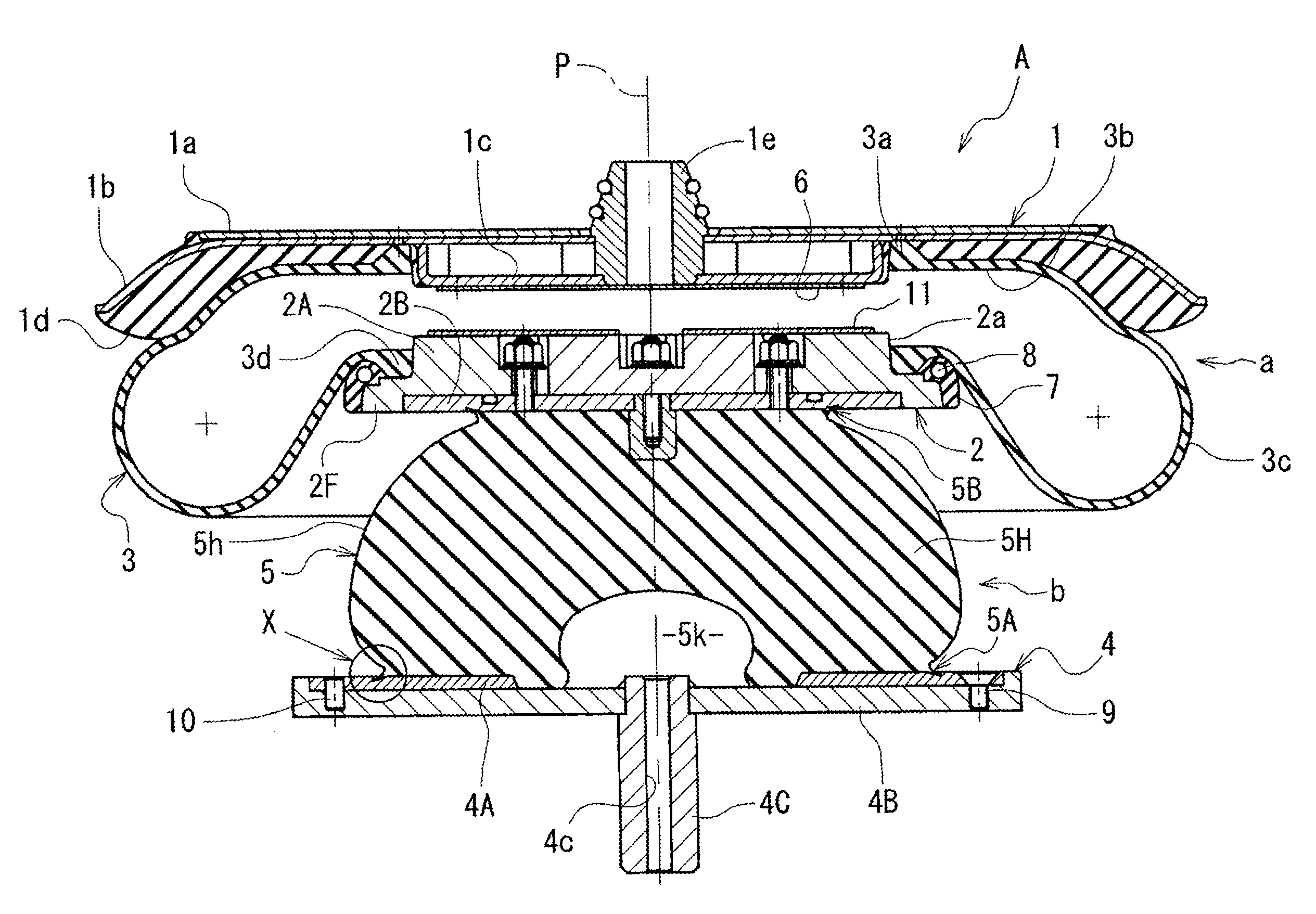
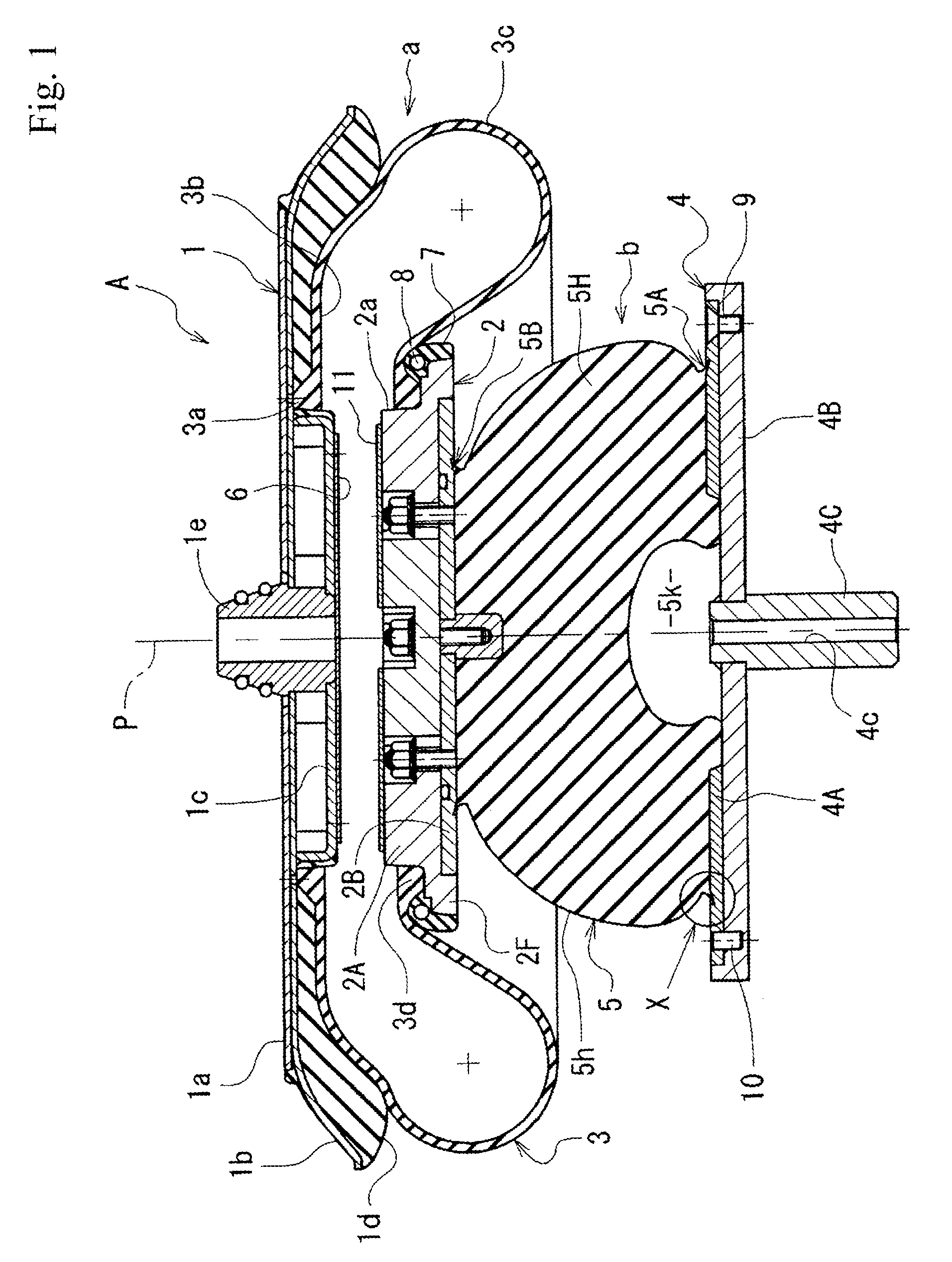
[0026]FIG. 1 and FIG. 2 show an air spring for railroad cars (hereinafter simply referred to as “air spring”) A. This air spring A is configured to include an air spring part a formed by an upper support 1 on the vehicle body side, an intermediate support 2 arranged therebelow, and a diaphragm 3 made of rubber (one example of an elastic material) extending between the former two, and an elastic mechanism b formed by the intermediate support 2, a lower support 4 on the bogie side arranged therebelow, and an elastic member 5 interposed between the intermediate and lower supports. The upper support 1 is supported on a vehicle body of a railroad car (not shown) via a cylindrical boss 1e having a vertical center axis P in its center, while the lower support 4 is supported on a bogie (not shown) via a cylindrical shaft 4C having a center axis P in its center.

[0027]The upper support 1 is configured to be disc-shaped, with an upper disc 1a, a lower disc 1b, a bottomed cylindrical portion 1c...

embodiment 2

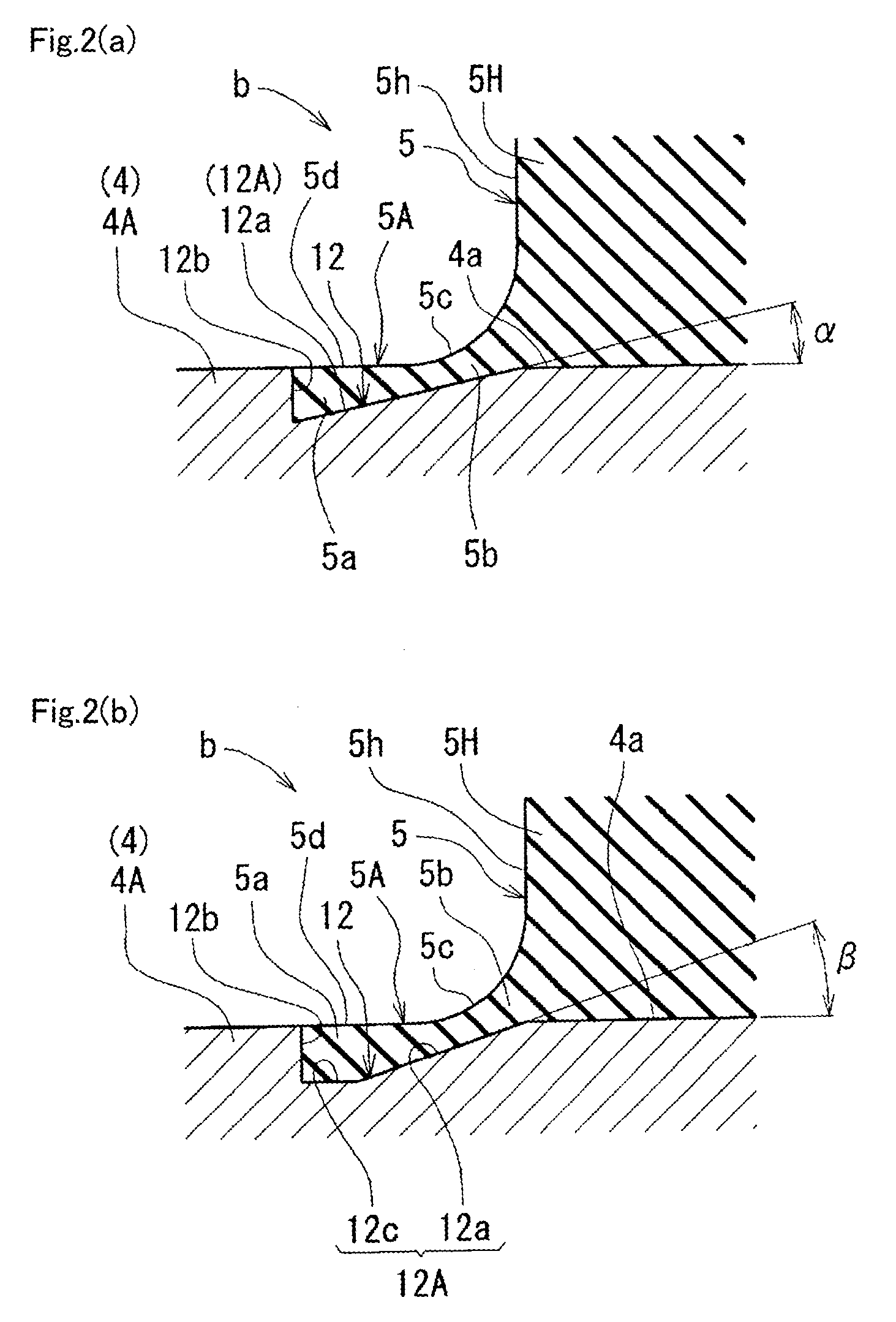
[0041]The downward enlarged end 5A may have a shape in which the edge line 5c shown in FIG. 2(a) is replaced with an upper large curved portion 13 and a lower small curved portion 14, as shown in FIG. 3(a). Namely, a large and small curved portions 13 and 14, which are curved surfaces warped in a circular arc (or quasi-circular arc) shape to be concave toward outside when viewed in cross section in the vertical direction, are formed continuously in two stages.

[0042]With this shape, when the elastic mechanism b undergoes a large lateral deformation and the downward enlarged end 5A bends, the zenith Z connecting the large and small curved portions 13 and 14 that are two stage curved surfaces will be the point of contraflexure, i.e., since the zenith Z where the thickness is large will be located at the deepest point of the bend, no deep wrinkles will be formed in the bending part. Accordingly, the downward enlarged end 5A will withstand repeated deformation and be free of chipping or ...

embodiment 3

[0044]The downward enlarged end 5A may have a shape in which the small curved portion 14 shown in FIG. 3 is replaced with a vertical wall 15 that forms a right angled corner between itself and the upper surface 5d of the annular outer circumferential portion 5a, as shown in FIG. 4(a).

[0045]The downward enlarged end 5A may be formed to correspond to the annular bottom 12A having an annular horizontal outer peripheral bottom 12c that is horizontal and continuous with the annular tapered bottom 12a on the radially outside, as shown in FIG. 4(b). This variation example of the small curved portion of Embodiment 3 shown in FIG. 4(b) provides the same effects (of a stronger bond) as the variation example of Embodiment 1 shown in FIG. 2(b).

Other Embodiments

[0046]The elastic mechanism b may be configured to have a laminated rubber structure formed by several layers of an elastic material such as rubber and one or more plate(s) of a hard material such as metal, wherein the layer and the plate...


PUM


Abstract

An air spring for railroad cars includes an air spring part formed by an upper support on a vehicle body side, an intermediate support arranged therebelow, and a diaphragm made of rubber and extending between the upper support and the intermediate support; and an elastic mechanism b formed by a rubber mass 5 interposed between the intermediate support and a lower support 4 on a bogie side arranged therebelow. The rubber mass 5 has an end in contact with the lower support 4 formed as an enlarged end 5A increasing in diameter as approaching the lower support 4 in a vertical direction. An outer circumferential portion of this enlarged end is fitted in and bonded to an annular groove 12 formed in the lower support 4, and the annular groove 12 has an annular bottom 12A inclined to decrease in height radially outwards to have an annular tapered bottom 12a.

Description

TECHNICAL FIELD[0001]The present invention relates to an air spring for railroad cars, and more particularly to an air spring for railroad cars including an air spring part formed by an upper support on a vehicle body side, an intermediate support arranged therebelow, and a diaphragm made of an elastic material and extending between the upper support and the intermediate support; and an elastic mechanism formed by an elastic member interposed between the intermediate support and a lower support on a bogie side arranged therebelow.BACKGROUND ART[0002]Air springs for railroad cars of this type have been known, as disclosed in Patent Document 1 and Patent Document 2. These springs are designed to include an elastic mechanism having a laminated rubber structure and integrally attached under an air spring part, so that the railroad car can exhibit a favorable suspension performance with these two types of springs combined and arranged in series.[0003]The rubber and a lower support that f...

Claims


Application Information

Patent Timeline
Patent Type & Authority Patents(United States)
IPC IPC(8): B61F5/08F16F13/00B61F5/02F16F9/04B60G11/62B61F5/10
CPCB61F5/08B60G11/62B61F5/02B61F5/10F16F9/0454F16F13/002F16F9/05
Inventor FUJIMOTO, KENJI
Owner NITTA CHEM IND PROD CO LTD
Why Eureka
Try Eureka