Slide rail device for vehicle

Active Publication Date: 2013-08-15
SHIROKI KOGYO CO LTD
View PDF5 Cites 15 Cited by
  • Summary
  • Abstract
  • Description
  • Claims
  • Application Information

AI Technical Summary

Benefits of technology

[0008]The present invention provides a slide rail device, for a vehicle, in which a biasing spring for attaching a handle to a lock-operation lever can be easily attached so as not to

Problems solved by technology

Therefore, assembling the torsion spring into the lock-operation lever is difficult.
Accordingly,

Method used


Image

  • Slide rail device for vehicle
  • Slide rail device for vehicle
  • Slide rail device for vehicle

Examples


Example

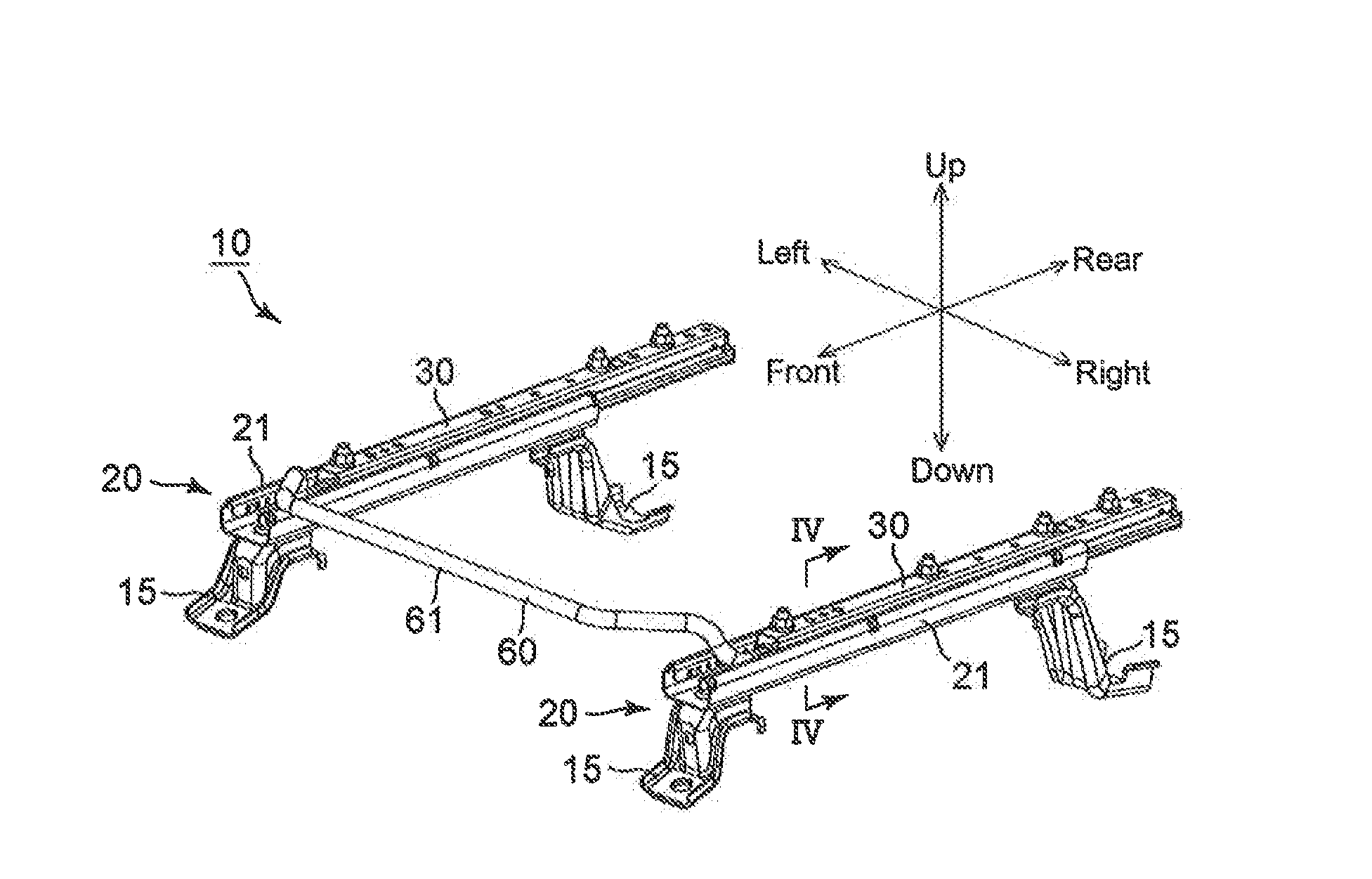
[0044]A first embodiment of the present invention will be hereinafter discussed with reference to the drawings. Directions described in the following description are defined based on the directions of the arrows shown in the drawings.

[0045]A slide rail device 10 is installed onto a vehicle interior floor of an automobile (vehicle), not shown in the drawings, and a seat (not shown) is fixed onto the upper side of the slide rail device 10 (upper rail 30).

[0046]The detailed structure of the slide rail device 10 will be discussed hereinafter.

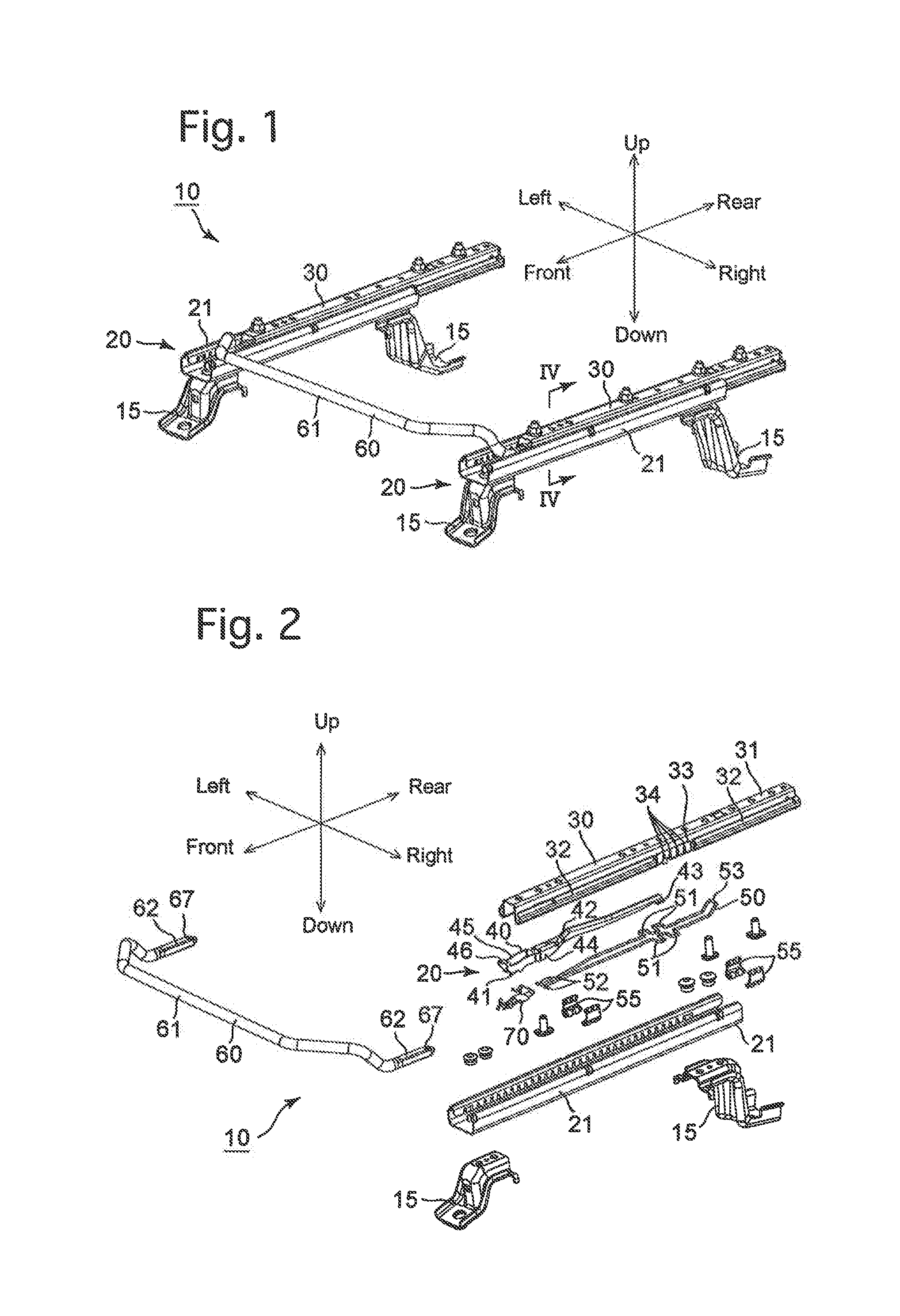
[0047]The slide rail device 10 is provided, as large components thereof, with a pair of left and right rail units 20 and a loop handle 60 which connects the front ends of the left and right rail units 20. The left and right rail units 20 are mutually bilaterally symmetrical while the loop handle 60 has a bilaterally-symmetrical shape, and therefore, the slide rail device 10 is bilaterally symmetrical as a whole.

[0048]The left and right rail units 20...

Example

[0080]A second embodiment according to the present invention will be hereinafter discussed with reference to FIGS. 19 through 23. Note that members that are the same as those of the first embodiment are designated with the same numerals, and detailed explanations thereof have been omitted.

[0081]In a slide rail device 20″ of the second embodiment, a lock lever (lock-operation lever) 85 is provided instead of the lock-release lever 40 of the first embodiment. The fundamental structure of the lock lever 85 is that same as that of the lock-release lever 40, and is likewise provided with left and right side walls 41, spring-hook grooves 44, a roof hole 45, an upper support member 46, spring-hook recesses 47, and lower support portions 48. The loop handle 60 is connected to the front end portion of the lock lever 85. Whereas, the rear end portion of the lock lever 85 is provided with a left and right pair of horizontal lock-plates 86. As shown in the drawings, each of the horizontal lock-...


PUM


Abstract

A slide rail device for a vehicle includes a lower rail; an upper rail supported on the lower rail to be slidably movable relative thereto; a lock mechanism between the upper and lower rails; a lock-operation lever inserted into the upper rail; a rotational supporter supporting the lock-operation lever to be rotatable between locked and unlocked positions; a handle; a biasing spring having an engaging portion which engages with the lock-engaging portion so that the engaging portion is immovable relative to the lock-engaging portion wherein the biasing spring supports the rear-end portion of the handle; and a spring support portion, provided on the upper rail, which is positioned immediately below the biasing spring and prevents the biasing spring from falling downward from an underside opening of the lock-operation lever when the rotational supporter supports the lock-operation lever.

Description

BACKGROUND OF THE INVENTION[0001]1. Field of the Invention[0002]The present invention relates to a slide rail device, for a vehicle, which supports a seat in a slidable manner.[0003]2. Description of Related Art[0004]A slide rail device for a vehicle which is disclosed in Japanese Unexamined Patent Application No. 2011-230717 is provided with a pair of left and right lower rails extending in a forward / rearward direction (of the vehicle) and fixed to a floor of the vehicle; a pair of left and right upper rails which support a seating portion of a seat and are slidably supported by the pair of left and right lower rails; a lock mechanism provided between the upper rails and the lower rails which restricts the sliding movement of the upper rails and releases sliding movement restriction of the upper rails; a pair of left and right lock-operation levers (lock-release levers) which are respectively inserted inside the upper rails and each are open at the front end and lower end thereof; ...

Claims


Application Information

Patent Timeline
IPC IPC(8): B60N2/08B60N2/07
CPCB60N2/0705B60N2/0715B60N2/07B60N2/0875B60N2/08B60N2/0818
Inventor HAYASHI, NAOKI
Owner SHIROKI KOGYO CO LTD
Why Eureka
Try Eureka