Illuminated keyboard providing high and uniform luminosity

Inactive Publication Date: 2013-08-15
ZIPPY TECH
View PDF7 Cites 0 Cited by
  • Summary
  • Abstract
  • Description
  • Claims
  • Application Information

AI Technical Summary

Benefits of technology

The present invention provides an illuminated keyboard that has high and uniform luminosity. It includes a keyboard portion with multiple key units arranged in parallel rows and a substrate to hold the key units. A light guide element is located on the substrate and includes a light guide portion in a horizontal mounting space and two light projecting portions in a vertical projection space. Each light projecting portion has a transparent zone to project light to the key unit assembly. The light guide element provides a greater light emission area, and the multiple key units in parallel rows form multiple key unit assemblies, which allows for direct projection of light to the key unit assembly to provide uniform luminosity for the key unit assembly.

Problems solved by technology

However, it also has drawbacks, such as the light guide strip is too thin and located between a plurality of key unit assemblies that are arranged in multiple rows.
When the transparent zone projects light at the preset angle to the key unit assemblies, a portion of light would be lost outside the key unit assemblies and results in insufficient luminosity of the keyboard.
Fabrication process and cost of the light guide strip increase significantly.

Method used


Image

  • Illuminated keyboard providing high and uniform luminosity
  • Illuminated keyboard providing high and uniform luminosity
  • Illuminated keyboard providing high and uniform luminosity

Examples


second embodiment

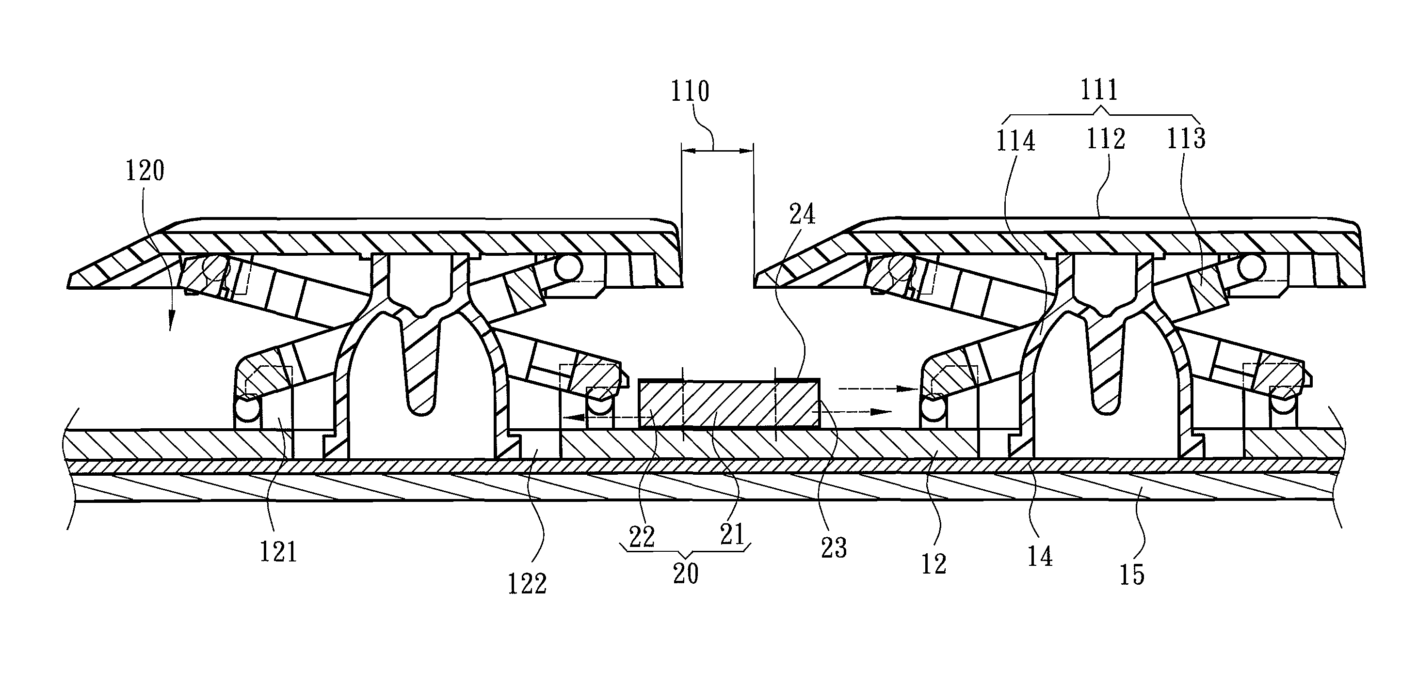
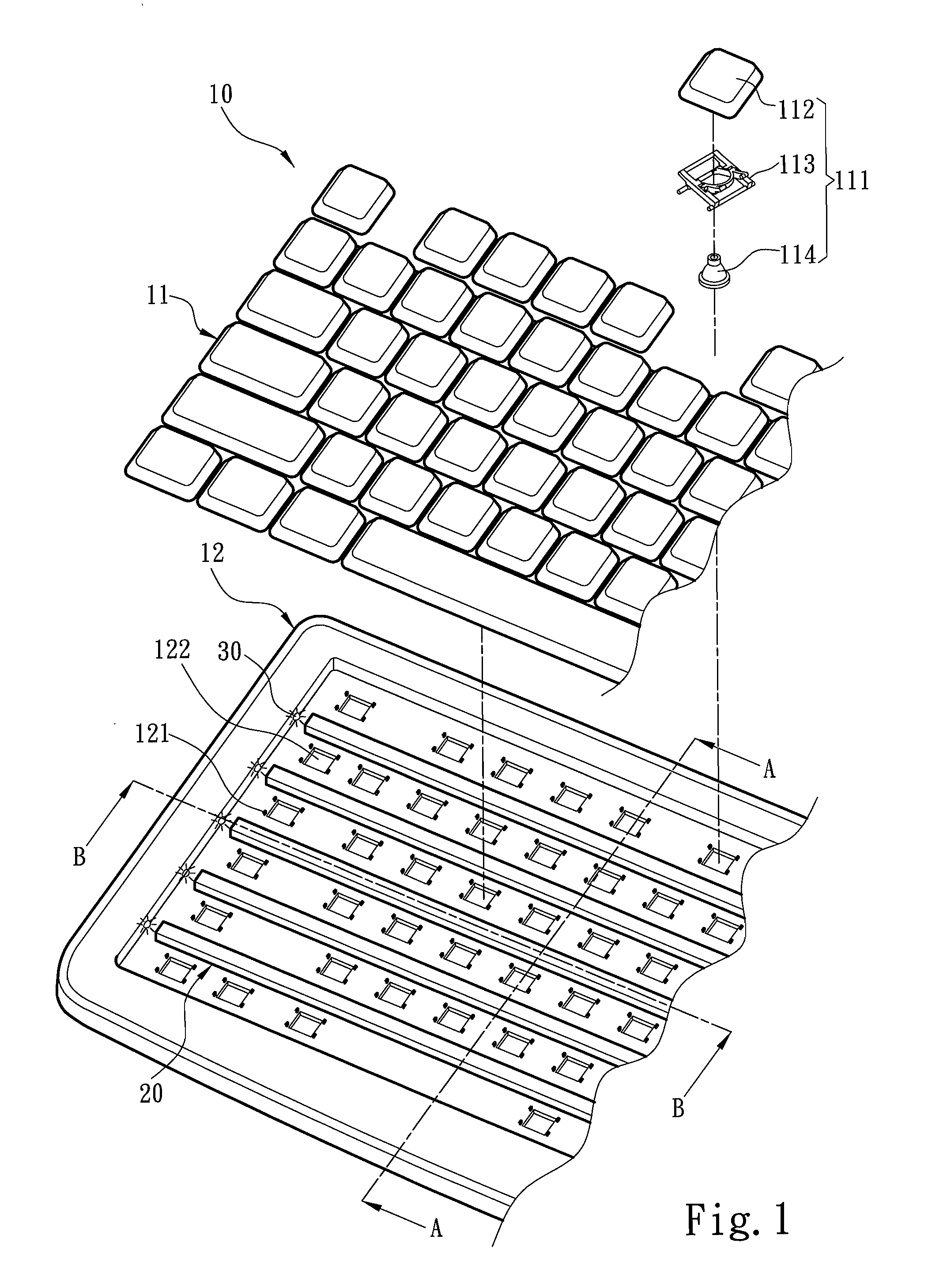
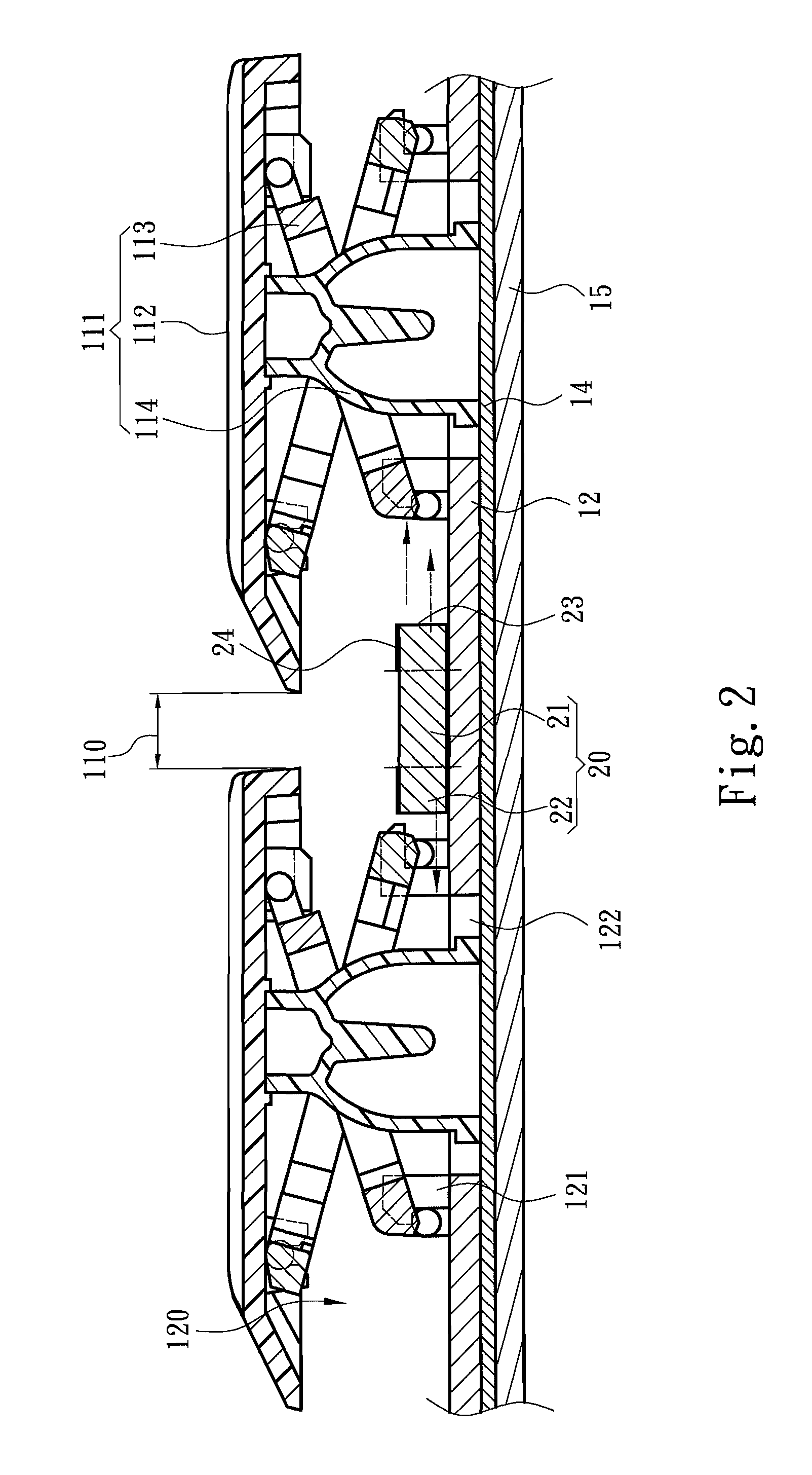
[0039]Please refer to FIG. 4 for a The transparent zone 23 of the light guide element 20 includes at least one light emitting groove 231 corresponding to the key units 111. The light emitting groove 231 has an inner wall to condense light and project the light outwards. The light projecting direction of the light emitting groove 231 can be changed by altering the three dimensional profile thereof without being restricted by the three dimensional structure of the light projecting portion 22.

third embodiment

[0040]Please refer to FIG. 5 for the light guide element. The transparent zone 23 includes two types of light emitting grooves 231, one has a triangular cross section and another has a rectangular cross section that are perpendicular to the extending direction of the light guide element 21 and formed at different locations on the light projecting portion 22. The light emitting groove 231 with the triangular cross section is located at one edge of the light projecting portion 22 to project the light upward in an inclined manner, while another light emitting groove 231 with the rectangular cross section is located at a side wall of the light projecting portion 22 to project the light outwards in a parallel fashion. Aside from the two types of the light emitting grooves 231, the cross section of the light emitting groove 231 perpendicular to the extending direction of the light guide element 21 can also be formed in a polygonal, semicircular or irregular shape. With the light emitting ...


PUM


Abstract

An illuminated keyboard providing high and uniform luminosity includes a keyboard portion and at least one light guide element. The keyboard portion includes a plurality of key units and a substrate to hold the key units. The key units are arranged in parallel rows each having multiple key units to form a key unit assembly. The key unit assembly is spaced from the substrate to form a vertical projection space, and any two neighboring key unit assemblies form a horizontal mounting space. The light guide element includes a light guide portion located in the horizontal mounting space and two light projecting portions located in the vertical projection space. Each light projecting portion has at least one transparent zone to project light transmitted by the light guide portion into the vertical projection space to provide uniform luminosity for the key unit assembly.

Description

FIELD OF THE INVENTION[0001]The present invention relates to an illuminated keyboard and particularly to an illuminated keyboard to provide high and uniform luminosity.BACKGROUND OF THE INVENTION[0002]Keyboard is a command output device of a computer system. Its design mainly aims to allow users to comfortably and accurately enter command signals. In a dim environment, the users who are not familiar with the symbols or characters on the keycaps cannot enter the command signals quickly. In order to help the users to recognize more clearly the legends on the keycaps in the dim environment, illuminated keyboards have been developed to meet such purpose.[0003]Some conventional illuminated keyboards adopt a light guide plate as a lighting element, such as U.S. Pat. Nos. 6,648,530, 6,860,612 and 7,531,764, and R.O.C. patent Nos. 509955, 516671, 587800 and 594546. They mainly use a light emitting back panel such as an electroluminescent sheet, optical fiber panel or the like to replace a g...

Claims


Application Information

Patent Timeline
IPC IPC(8): G09F13/04
CPCG06F3/0202H01H13/83H01H2219/062H01H2219/06H01H3/125
Inventor CHOU, CHIN-WENHWA, CHIN-HSIUHUANG, YU-CHUN
Owner ZIPPY TECH
Why Eureka
Try Eureka