Method for optically scanning an edge in or on a surface region

a surface region and optical scanning technology, applied in the field of optically measuring or scanning an edge, can solve the problems of difficult exact detection of the location of the edge in the camera image, and achieve the effects of reducing the necessary measuring duration, reducing the necessary measurement time, and reducing the calculation capacity

Active Publication Date: 2013-08-15
CARL MAHR HLDG
View PDF4 Cites 11 Cited by
  • Summary
  • Abstract
  • Description
  • Claims
  • Application Information

AI Technical Summary

Benefits of technology

[0019]It is also of advantage if at least part of the determined weighting factors are stored in memory or allocated to the actually measured object or surface region or type of object or type of object surface region. The properties of the reflectivity images are essentially the same in approximately equally oriented surface regions. This knowledge can later be reused in the edge measurement of objects or object surface regions of the same type, for example, when repeated edge measurements are performed on tools and workpieces that are similar or identical. Sequences of camera images that have not resulted in a usable reflectivity image due to the illumination condition need not be recorded again. In later camera measurements of objects or object surface regions of the same type it is sufficient to record the sequences whose reflectivity images have been used in the determination of the resulting reflectivity image, i.e., those that have been allocated a weighting factor greater than zero, for example. For example, it is also possible to prespecify a minimum weighting factor; during later edge measurements of the same types of objects only those sequences are recorded whose reflectivity image of other measurements had previously received a weighting factor that correspon

Problems solved by technology

Until now, the exact detection of the location of an edge in the camera image has been diffic

Method used


Image

  • Method for optically scanning an edge in or on a surface region
  • Method for optically scanning an edge in or on a surface region
  • Method for optically scanning an edge in or on a surface region

Examples


Embodiment Construction

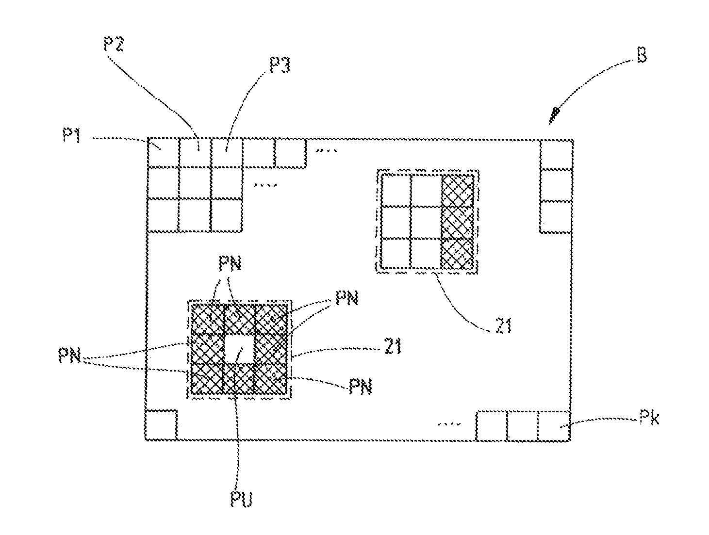
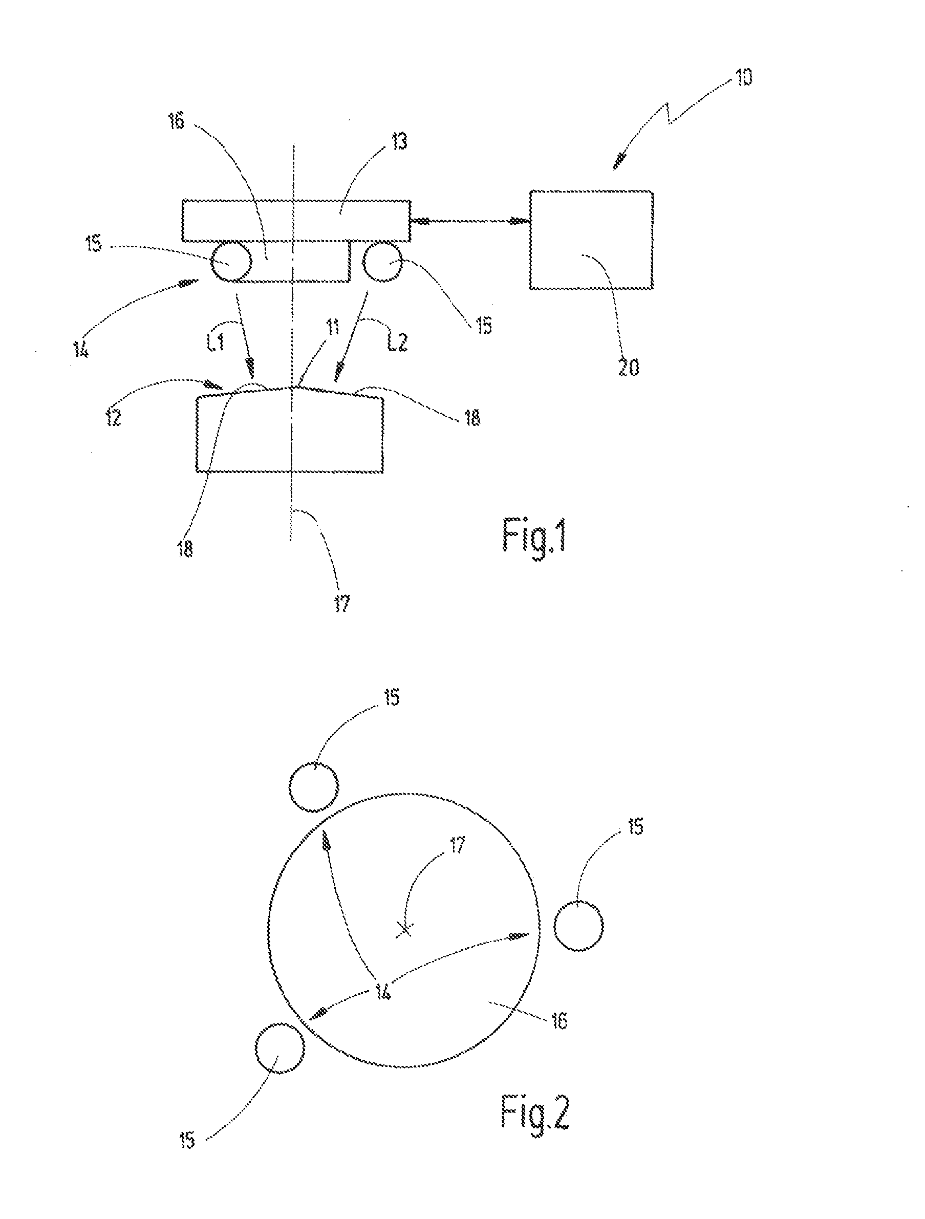
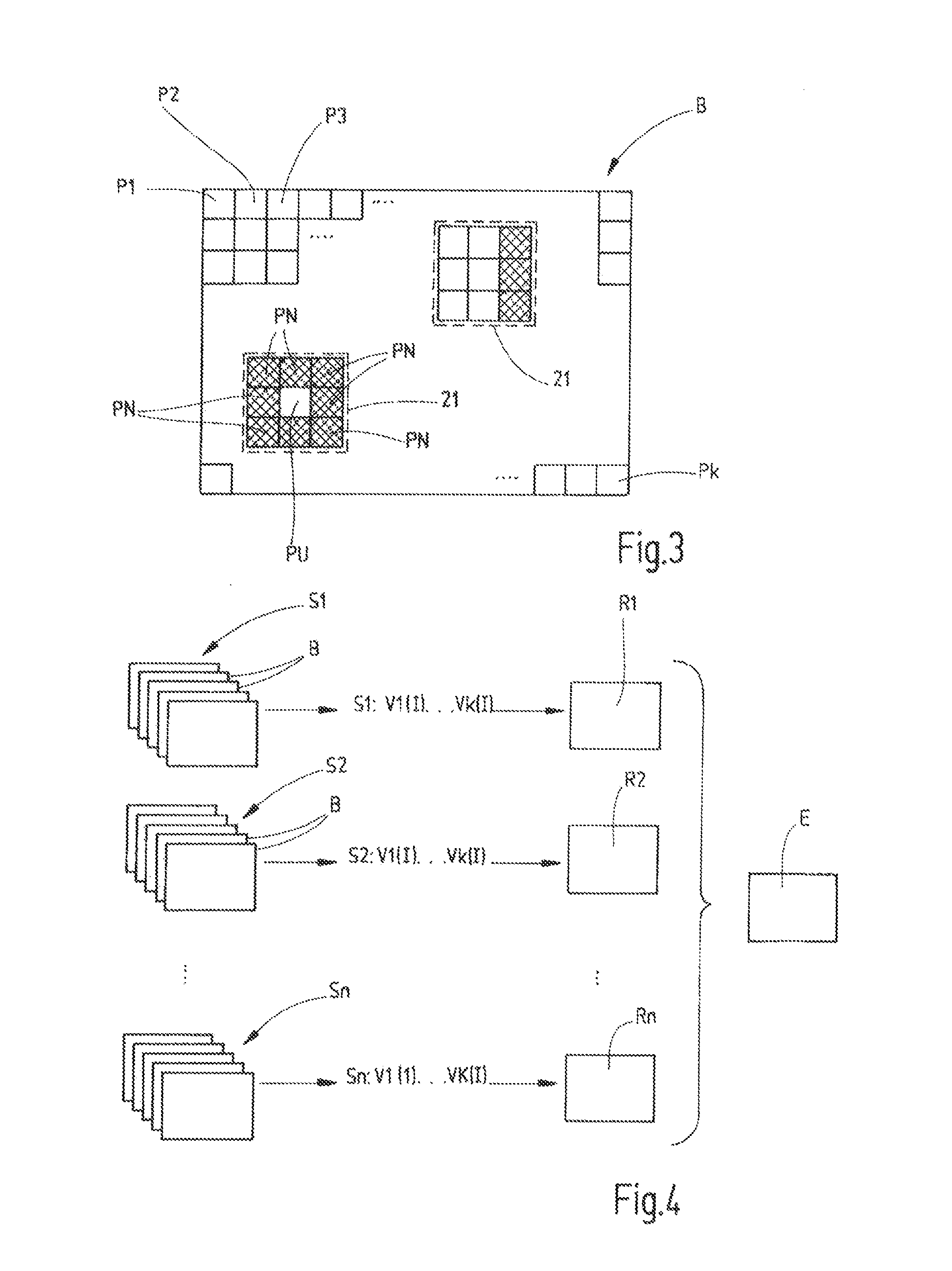
[0030]FIGS. 1 and 2 show a device 10 for optically scanning an edge 11 of an object surface region 12 of an object 9. In accordance with the example, two partial regions 18 are contiguous to the edge 11 to be detected in the object surface region 12.

[0031]The device 10 comprises a camera 13, preferably a matrix camera. In addition, the device 10 comprises an illumination arrangement 14 comprising a plurality of light sources 15. Referring to the exemplary embodiment described here, the light sources 15 are distributed around the lens 16 of the camera 13 or its optical axis 17. The distance of the light sources 15 from the optical axis 17 may be the same.

[0032]The camera 13, as well as the illumination arrangement 14, are enabled via a control arrangement 20. The control arrangement 20 can adjust the camera settings such as, for example, location of focus, exposure time, aperture. In addition, the control arrangement 20 enables the illumination arrangement 14. The control arrangement...


PUM


Abstract

A method for ascertaining the position of an edge in or on an object surface region of interest by optical scanning. The reflectivity of the object surface region is evaluated. Light is emitted onto the object surface region under different illumination conditions, in particular different light incidence directions, and in each illumination condition a sequence S1 to Sn of camera images B is recorded. Each camera image B of a sequence S1 to Sn is recorded at another illumination intensity I. Subsequently in each case one reflectivity image R1 to Rn is produced from a plurality of or from all camera images B of a sequence S1 to Sn. Thereafter, a resulting reflectivity image E is produced from a plurality of or from all reflectivity images R1 to Rn by weighted addition, in which resulting reflectivity image E the position of an edge is determined.

Description

CROSS-REFERENCE TO RELATED APPLICATION[0001]This is a continuation-in-part application of pending international application PCT / EP2011 / 066135 filed Sep. 16, 2011 and claiming the priority of German Application No. 10 2010 037 746.5 filed Sep. 23, 2010.BACKGROUND OF THE INVENTION[0002]The present invention relates to a method for optically measuring or scanning an edge located within or limited by a surface region. To accomplish this, a camera can be used for recording the surface region of interest, said region comprising at least two partial regions that are contiguous to the edge. Subsequently, the edge location can be ascertained based on one or several recordings using at least one edge location criterion for the detection of the position of the edge.[0003]A method for edge measuring has been known, for example, from publication DE 102 15 135 A1, This method is to be used for the automatic detection of control information for values influencing the camera image in order to be ab...

Claims


Application Information

Patent Timeline
IPC IPC(8): G06K9/46
CPCG06K9/4604G01B11/028
Inventor NEHSE, UWEBUECHNER, MARCO
Owner CARL MAHR HLDG
Why Eureka
Try Eureka