Caster assembly

a technology of casters and parts, applied in the field of casters, can solve the problems of casters and objects being unstable, unplanned movement cannot be completely expelled by the simple brake,

Inactive Publication Date: 2013-08-22
DERSHENG
View PDF2 Cites 19 Cited by
  • Summary
  • Abstract
  • Description
  • Claims
  • Application Information

AI Technical Summary

Benefits of technology

[0007]The main object of the present invention is to provide a brake to a caster to prevent both rolling and spinning of wheel of the caster.

Problems solved by technology

However, unexpected movement can not be completely expelled by the mere brake.
Therefore, the caster and the object carried would be unstable even the brake is activated.

Method used


Image

  • Caster assembly
  • Caster assembly
  • Caster assembly

Examples


Embodiment Construction

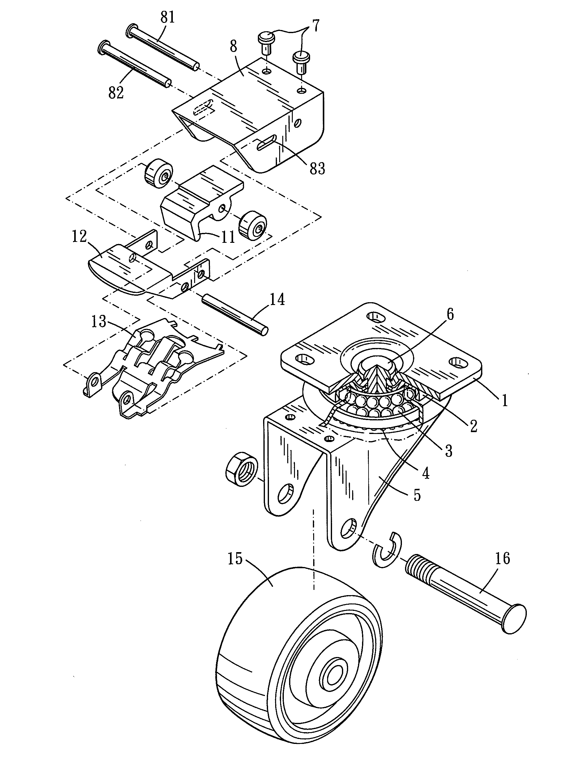
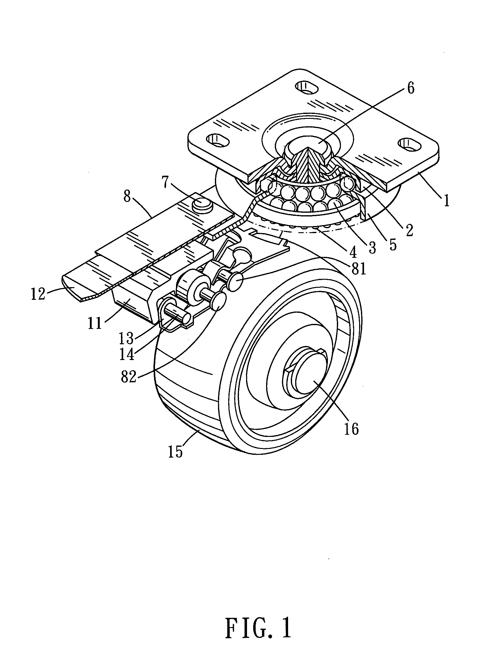
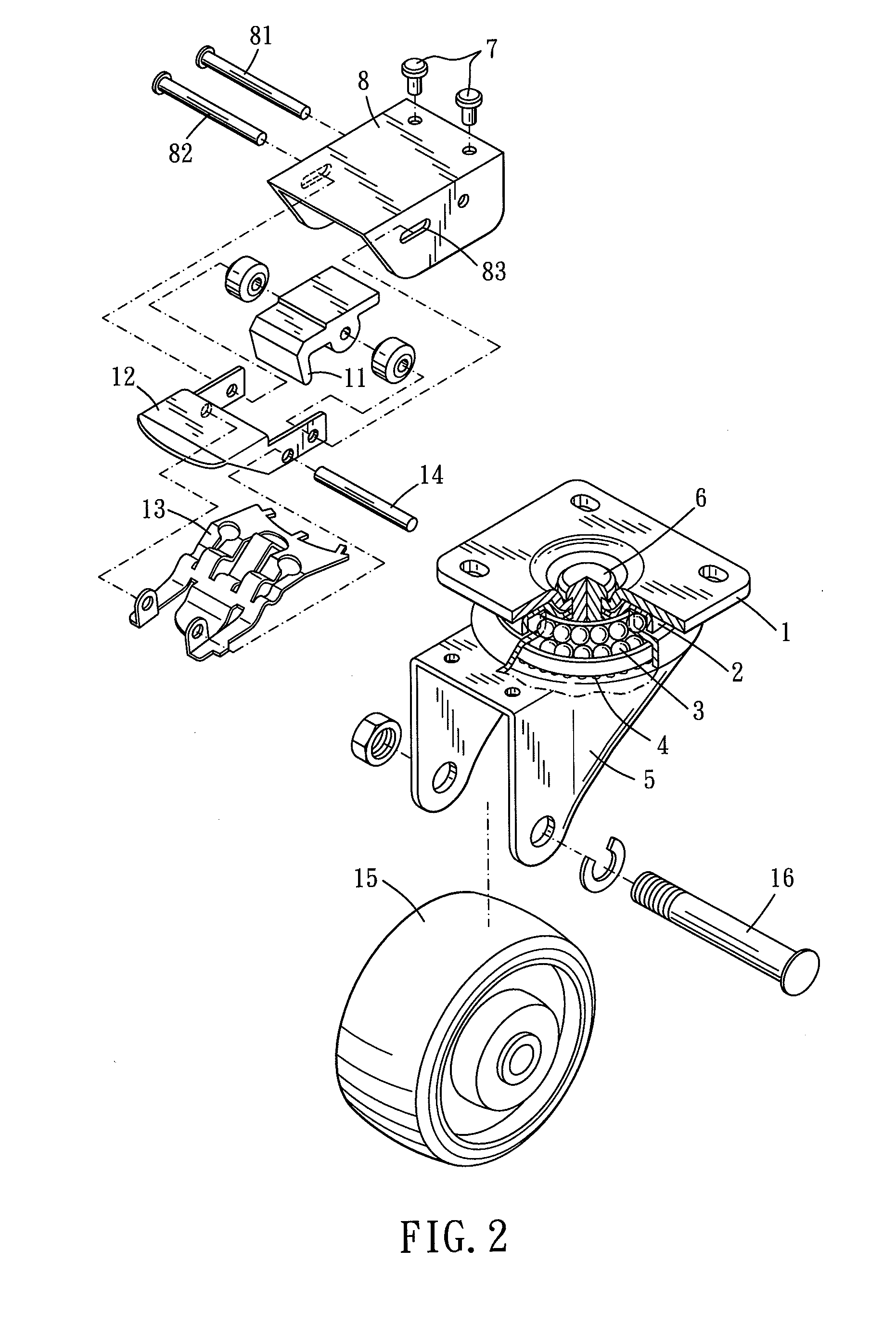
[0023]Please refer to FIG. 1 and FIG. 2 for a first embodiment of the present invention. The caster assembly of the present embodiment is provided for wagon, carriage, luggage box, table, or chair. Supporting and moving smoothly is then achieved. The caster assembly includes a fixation base 1, a rotary base, a wheel 15, and a break mechanism.

[0024]The fixation base 1 is provided for being mounted to other objects, such as wagon or carriage. Therefore, the fixation base 1 is formed with several fixation holes which are provided for screws or rivets to penetrate therethrough. The fixation base 1 is further provided with bearing 2, 3 which is suitable for burdening vertical pressing force. The fixation base 1 is provided with protrusions 4 on the bottom thereof. As shown in FIG. 3 to FIG. 5, the protrusions 4 are spaced from others and are annularly arranged. Gaps are defined between any two adjacent protrusions 4.

[0025]Please refer to FIG. 1. The rotary base is rotatably disposed on t...


PUM


Abstract

A caster assembly of the present invention includes a fixation base, a rotary base which is rotatably disposed on the fixation base, a wheel which is rotatably disposed on the rotary base, and a brake mechanism. The brake mechanism is disposed on the rotary base. The brake mechanism can be activated to abut against the wheel and the fixation base, so that rotations of the rotary base and the wheel are obstructed. Thus, stably fixation function is provided.

Description

BACKGROUND OF THE INVENTION[0001]1. Field of the Invention[0002]The present invention relates to a caster provided on table, chair, or luggage box for moving.[0003]2. Description of the Prior Art[0004]Caster is usually provided on (under, exactly) furniture for supporting and moving purpose. For fixation purpose, casters are usually provided with brake. Unexpected movement caused by relief or external force is then prevented.[0005]However, unexpected movement can not be completely expelled by the mere brake. When brake of the caster is activated, wheel of the caster is prevented from only rolling. The wheel can still spin if suitable external force is exerted thereon. Therefore, the caster and the object carried would be unstable even the brake is activated.[0006]The present invention is, therefore, arisen to obviate or at least mitigate the above mentioned disadvantages.SUMMARY OF THE INVENTION[0007]The main object of the present invention is to provide a brake to a caster to preve...

Claims


Application Information

Patent Timeline
Patent Type & Authority Applications(United States)
IPC IPC(8): B60B33/00
CPCB60B33/0018B60B33/0039Y10T16/184B60B33/0081B60B33/021B60B33/0068
Inventor CHEN, CHING-TSUN
Owner DERSHENG
Why Eureka
Try Eureka