Fabricated steel structure beam and column connection joint and construction method

A technology of beam-column connection and steel structure, which is applied in the direction of building components, building structures, protective buildings/shelters, etc., can solve problems such as falling off and low connection strength, and achieve the effect of consuming earthquake energy

Inactive Publication Date: 2019-10-08
孔瑞清
View PDF8 Cites 12 Cited by
  • Summary
  • Abstract
  • Description
  • Claims
  • Application Information

AI Technical Summary

Problems solved by technology

The disadvantage of this connection technology is that the connection strength is not high and it is easy to fall off.

Method used


Image

  • Fabricated steel structure beam and column connection joint and construction method
  • Fabricated steel structure beam and column connection joint and construction method
  • Fabricated steel structure beam and column connection joint and construction method

Examples


Embodiment 1

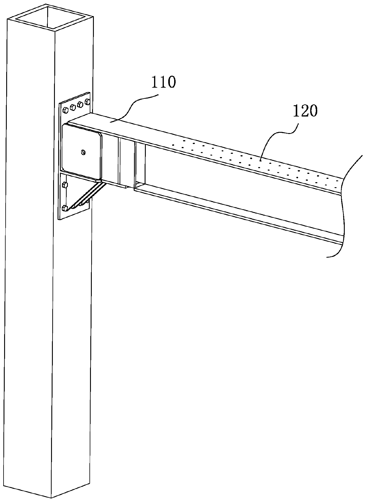
[0049] The steel beam in this embodiment is an I-shaped steel structure, which is the same as a common I-shaped beam. The steel beam in this embodiment is also composed of a web and a flange, wherein a hollowed-out circular hole can also be set on the web. To further reduce the self-weight of the steel beam, the round hole is composed of a large round hole and a small round hole. This hollowed-out structure can further optimize the amount of steel used in steel structures without reducing the strength.

[0050] This embodiment is attached in conjunction with the instructions figure 1 To attach Figure 10 Give a detailed explanation.

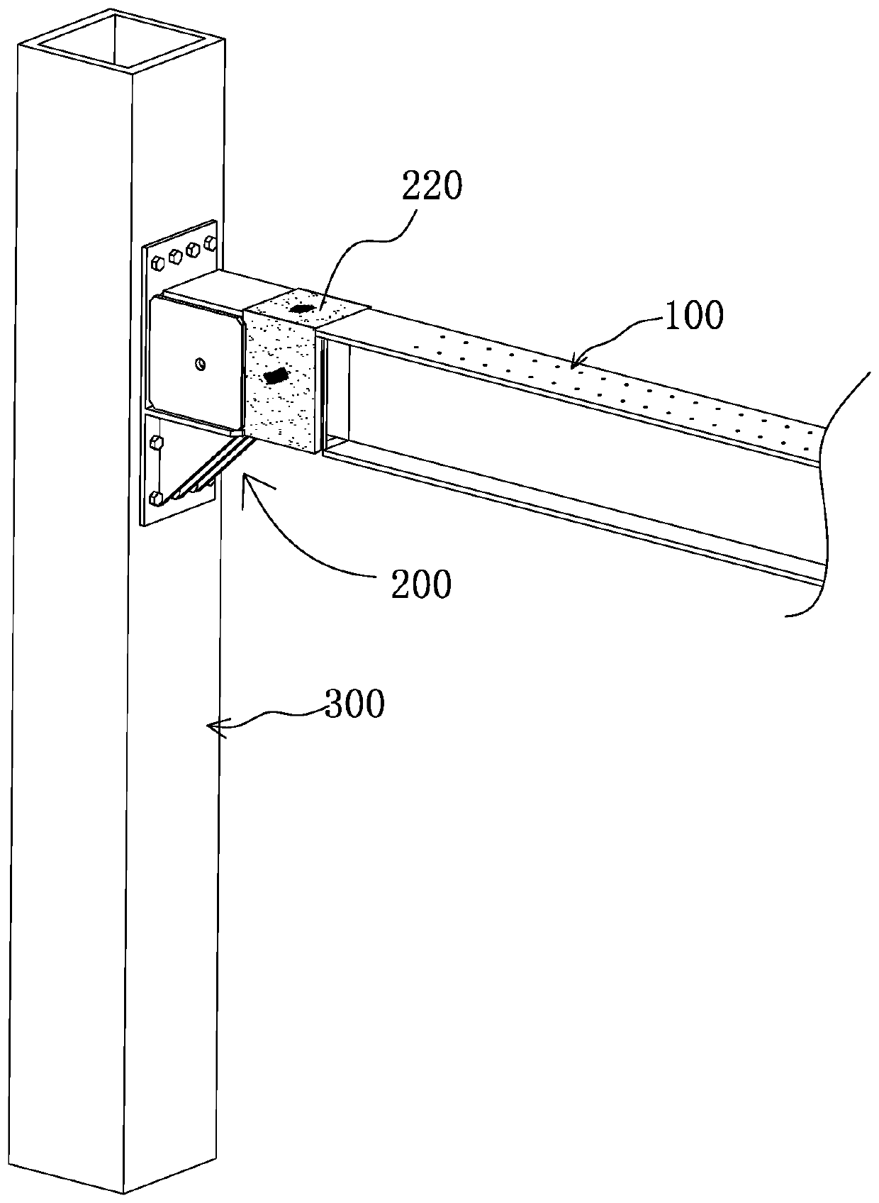
[0051] The two ends of the steel beam 100 are connecting parts, which are formed through optimized design. The connecting parts are used for special connection with the corbel to meet the requirements of use.

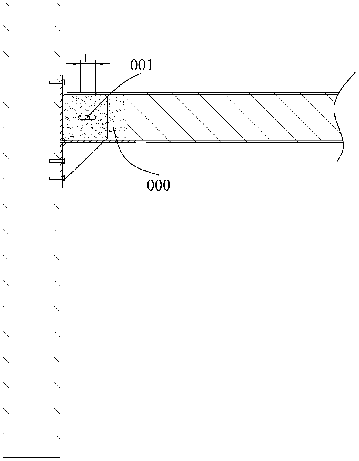
[0052]The corbel 200 is installed on the column 300 by welding or fixing. The corbel 200 is composed of a support part 210 and a moun...

Embodiment 2

[0069] As a way to improve, the separator can also adopt a structure with folds 1114, the structure of the separator can refer to Figure 11 , forming a connection with a certain degree of elasticity, this structure is more portable and more shock-resistant. This structure is suitable for the connection of steel beams and steel columns of light steel structures. At the same time, the structure of the folds can store more emulsified asphalt in the gaps of the folds to form a high-strength bond.

Embodiment 3

[0071] Referring to the figure, this embodiment can also achieve a more excellent installation effect. In this embodiment, after installation, a more excellent floor installation space can be formed. Specifically, the installation parts at both ends of the steel beam are designed to fold down The curved bending structure, and a plug-in structure is provided at the position of the bending structure. In this way, sufficient installation space is formed at the connecting parts at both ends of the steel beam, making the connecting parts easier to install.


PUM


Abstract

The invention discloses a fabricated steel structure beam and column connection joint and a construction method thereof and provides a novel joint structure. The fabricated steel structure beam and column connection joint comprises a steel beam, a steel column and a bracket. The bracket is composed of a supporting part and an installation part, wherein the steel beam and the installation part of the bracket are in insertion connection through a comb structure, and an extensible and retractable space exits for the insertion connection in the length direction of the steel beam; and a gap of theinsertion connection is filled with emulsified asphalt, and the periphery of the insertion connection is wrapped with carbon fiber gridding cloth. According to the fabricated steel structure beam andcolumn connection joint and the construction method, the comb-shaped insertion structure is in a fixed connection state under a non-earthquake state, and a relatively stable fixed state is formed. When a strong earthquake happens, the insertion connection part relatively moves, slides and shifts, an energy consumption effect is achieved at the insertion connection part, that is, the connection joint of the insertion structure has a certain effect of counteracting and consuming earthquake energy, and the steel structure building per se is more resistant to earthquakes.

Description

technical field [0001] The invention relates to the technical field of steel structure building installation and construction, in particular to a connecting node of beams and columns. Background technique [0002] Prefabricated steel structure buildings are getting more and more attention. In steel structures, the connection of steel beams and steel columns is the most common and the most demanding node. [0003] The current connection technologies for steel beams and steel columns mainly include three types. The first is full-welded connection, that is, the flange and web of the steel beam are welded to the steel column by welding. Usually, this fully-welded structure On-site welding work was required, and the junctions of steel beams and columns were reinforced with stiffeners. This fully welded connection method has the advantage of low cost, but the risk and cost of high-altitude welding operations are relatively high. Therefore, this type of fully welded connection is...

Claims


Application Information

Patent Timeline
Patent Type & Authority Applications(China)
IPC IPC(8): E04B1/24E04B1/58E04B1/98E04H9/02E04G21/14
CPCE04B1/2403E04G21/14E04H9/024
Inventor 不公告发明人
Owner 孔瑞清
Why Eureka
Try Eureka