
Automatic telegraph pole installing machine special for power distribution network power transmission line

An automatic installation and transmission line technology, applied in the field of distribution network, can solve the problems of slow installation speed, poor installation effect, low work efficiency, etc., and achieve the effect of fast installation speed, continuous installation and high work efficiency

Inactive Publication Date: 2017-05-31
储德姣
View PDF6 Cites 13 Cited by
  • Summary
  • Abstract
  • Description
  • Claims
  • Application Information

AI Technical Summary

Problems solved by technology

[0003] In order to solve the above problems, the present invention provides an automatic installation machine for electric poles dedicated to transmission lines in distribution networks, which can solve the problems of complicated operation, high labor intensity, slow installation speed, and difficult installation of existing electric poles for transmission lines. Poor effect and low work efficiency and other problems, can realize the automatic installation function of utility poles, without manual operation, has the advantages of simple operation, low labor intensity, fast installation speed, good installation effect and high work efficiency

Method used


Image

  • Automatic telegraph pole installing machine special for power distribution network power transmission line
  • Automatic telegraph pole installing machine special for power distribution network power transmission line
  • Automatic telegraph pole installing machine special for power distribution network power transmission line

Examples


Embodiment Construction

[0028] In order to make the technical means, creative features, goals and effects achieved by the present invention easy to understand, the present invention will be further described below in conjunction with specific illustrations.

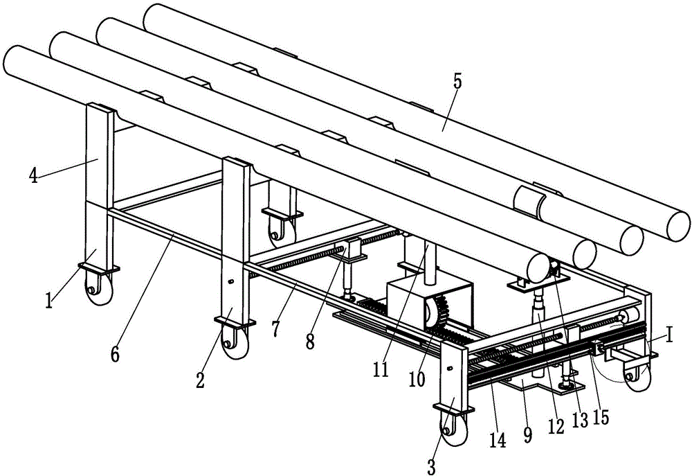
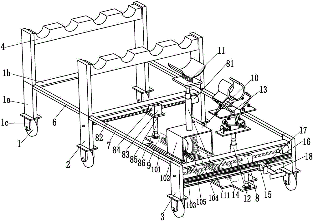
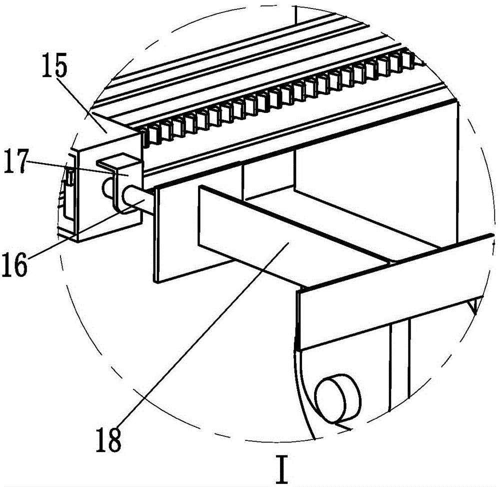
[0029] Such as Figure 1 to Figure 6 As shown, an automatic installation machine for utility poles dedicated to distribution network transmission lines includes a first traveling frame 1, a second traveling frame 2 and a third traveling frame 3, and the upper ends of the first traveling frame 1 and the second traveling frame 2 are Each rod frame 4 is welded, and each rod frame 4 is evenly provided with a semicircular rod seat sunken downwards, and the semicircular rod seats on the first walking frame 1 and the second walking frame 2 are evenly installed There is a rod body 5, the first walking frame 1 and the second walking frame 2 are connected by two No. 1 crossbars 6, and the two No. 1 crossbars 6 serve as a fixed connection between the first...


PUM


Abstract

The invention relates to an automatic telegraph pole installing machine special for a power distribution network power transmission line. The automatic telegraph pole installing machine comprises a first walking frame, a second walking frame and a third walking frame, wherein a rod frame is welded to the upper end of the first walking frame and the upper end of the second walking frame respectively, and rod bodies are uniformly installed on the first walking frame and the second walking frame. A movable limiting mechanism is arranged on the second walking frame and the third walking frame respectively, fixed limiting plates are installed at the lower ends of the two movable limiting mechanisms, first driving mechanisms are installed on the fixed limiting plates, drive guiding mechanisms are installed at the upper ends of the first driving mechanisms, and the upper ends of the drive guiding mechanisms abuts against the lower end faces of the corresponding rod bodies. Hydraulic cylinders I are installed on the right sides of the upper end faces of the fixed limiting plates, and clamping and guiding mechanisms are installed at the top ends of the hydraulic cylinder I through flanges. The automatic telegraph pole installing machine can achieve a full-automatic telegraph pole installing function without manual operation and has the advantages of being simple and convenient to operate, low in labor intensity, high in installing speed, good in installing effect, high in working efficiency and the like.

Description

technical field [0001] The invention relates to the technical field of distribution network, in particular to an automatic pole installation machine for transmission lines of distribution network. Background technique [0002] The distribution network is composed of overhead transmission lines, cables, towers, distribution transformers, isolating switches, reactive power compensators and some auxiliary facilities. It plays an important role in the distribution of electric energy in the power network. The most important part of the existing overhead transmission line is mainly installed on the utility poles. Since electricity is indispensable in every place, the number of utility poles required is very large, so the installation requirements of utility poles are also very large. The existing installation of utility poles is mainly done by manual lifting, which has defects such as complex operation, high labor intensity, slow installation speed, poor installation effect and lo...

Claims


Application Information

Patent Timeline
IPC IPC(8): E04H12/34
CPCE04H12/34E04H12/345
Inventor 储德姣
Owner 储德姣
Learn More