Pin installation tool and installation method

A technology for installing tools and mounting holes, which is applied in the direction of manufacturing tools, hand-held tools, and supporting components of blades, etc., and can solve the problems of extremely difficult to find the fixing pin 2, easy falling off of the fixing pin 2, and difficult fixing

Pending Publication Date:
View PDF0 Cites 0 Cited by
  • Summary
  • Abstract
  • Description
  • Claims
  • Application Information

AI Technical Summary

Problems solved by technology

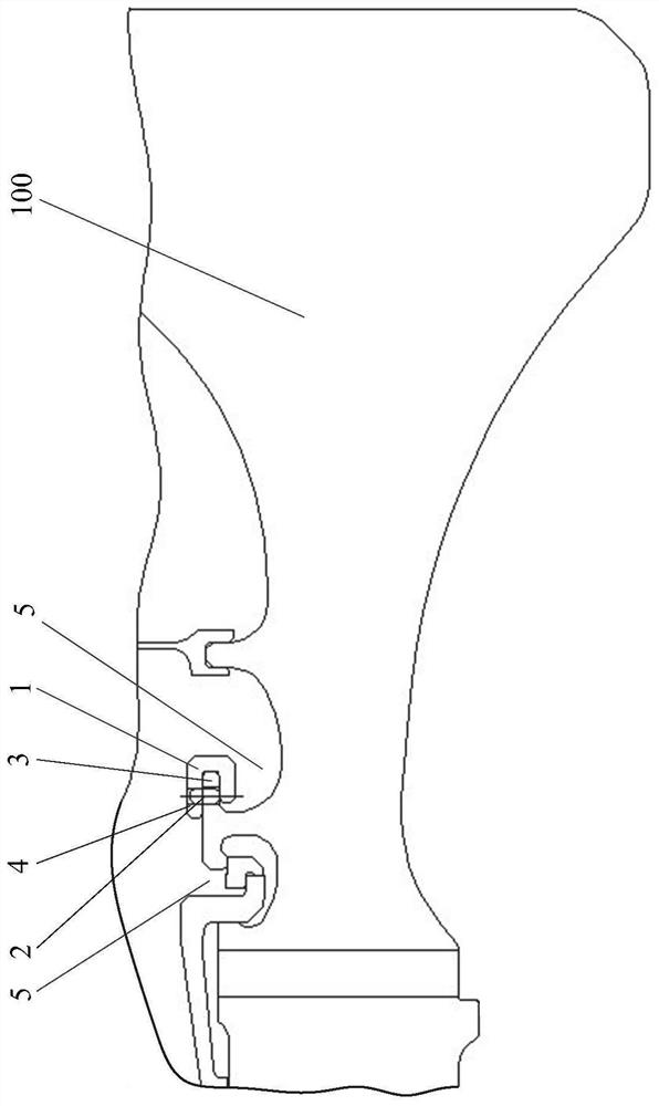
like figure 1 As shown, the balance weight 1 of the high-pressure turbine rotor 100 of the example model is fixed on the flange side 3 through the fixing pin 2. The diameter of the fixing pin 2 is less than 2 mm, and the height is less than 4 mm. It is a miniature part, because the fixing pin 2 is too small , it is difficult to fix, it is difficult to install manually, and the assembly efficiency is low
Since the shape and surface of the area near where the fixing pin 2 is installed is relatively complex, there are relatively complicated special-shaped grooves 5 on the inner and outer sides, and the fixing pin 2 is held by tweezers, and the fixing pin 2 is easy to fall off and fall into the grooves on the inner and outer sides 5, because the fixed pin 2 is too small, and the groove 5 is irregular and complex-shaped, once the fixed pin 2 falls into the groove 5 on both sides, it is extremely difficult to find the fixed pin 2 and remove it from the groove. Take out from slot 5

Method used


Image

  • Pin installation tool and installation method
  • Pin installation tool and installation method
  • Pin installation tool and installation method

Examples


Embodiment Construction

[0024] A variety of different implementations or examples for implementing the described subject technical solutions are disclosed below. In order to simplify the disclosure, the following describes the specific examples of each component and arrangement, of course, these are only examples, not limiting the protection scope of the present invention. For example, the description that the first feature described later in the description is formed on or above the second feature may include an embodiment in which the first and second features are formed through direct contact, and may also include an embodiment in which the first and second features are formed between the first and second features. Embodiments of additional features such that there may be no direct relationship between the first and second features. Additionally, reference numerals and / or letters may be repeated in different instances in these disclosures. This repetition is for brevity and clarity and does not i...


PUM


Abstract

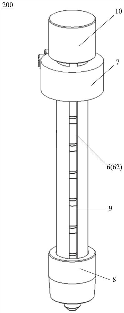
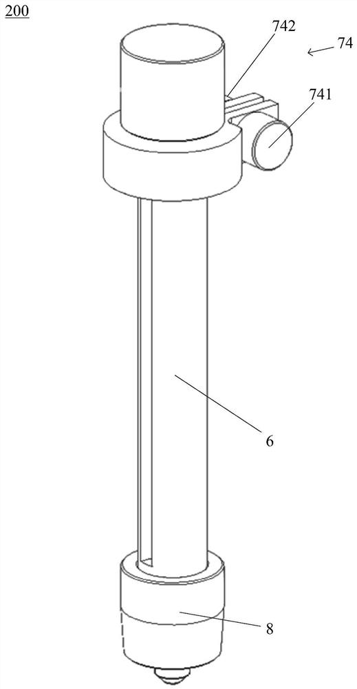
The invention provides a pin mounting tool and a pin mounting method, which can quickly, safely and reliably realize continuous mounting of a plurality of pins. In a pin mounting tool: an elongated conduit provides a space and a guide slot for accommodating a plurality of pins, the plurality of pins only being able to be placed in the space in an end-to-end manner; the pressing table comprises an annular part which surrounds the long and thin guide pipe and is provided with an opening, a guide section which extends inwards on the annular part and is in sliding fit with the guide groove, a pushing and pressing part arranged at the tail end of the guide section and a loosening and tightening device, the pushing and pressing part is located in the long and thin guide pipe and used for pushing and pressing the topmost pin in the multiple pins, and when the loosening and tightening device loosens the opening, the pushing and pressing part presses the topmost pin. The pressing table can slide on the slender catheter; the gripping device provides a scalable restricting channel to restrict the pin from sliding out of the elongate conduit, but permit the urging portion to urge the pin. The pin installation method comprises the steps that any pin installation tool is provided; placing a plurality of pins into the elongated conduit one by one; the pressing table is installed on the long and thin guide pipe, and the pushing and pressing part faces the upper end face of the topmost pin; the pins are inserted into the mounting holes one by one.

Description

technical field [0001] The invention relates to the technical field of engine assembly, in particular to a pin installation tool and an installation method. Background technique [0002] The high-pressure turbine rotor is an important part of an aero-engine. As a rotating part, the high-pressure turbine rotor must be dynamically balanced before it is installed on the engine. Adding counterweight is an important measure to eliminate the rotor imbalance. Such as figure 1 As shown, the balance weight 1 of the high-pressure turbine rotor 100 of the example model is fixed on the flange side 3 through the fixing pin 2. The diameter of the fixing pin 2 is less than 2 mm, and the height is less than 4 mm. It is a miniature part, because the fixing pin 2 is too small , It is difficult to fix, it is difficult to install manually, and the assembly efficiency is low. In the existing assembly mode, tweezers are used to pick up the fixing pin 2, and after aligning with the installation ...

Claims


Application Information

Patent Timeline
Patent Type & Authority Applications(China)
IPC IPC(8): B25B27/02F01D5/30F01D25/28
Inventor 胡一廷任家海史新宇杨波
Why Eureka
Try Eureka