
Roller module for input device

Inactive Publication Date: 2013-08-22
PRIMAX ELECTRONICS LTD
View PDF5 Cites 12 Cited by
  • Summary
  • Abstract
  • Description
  • Claims
  • Application Information

AI Technical Summary

Benefits of technology

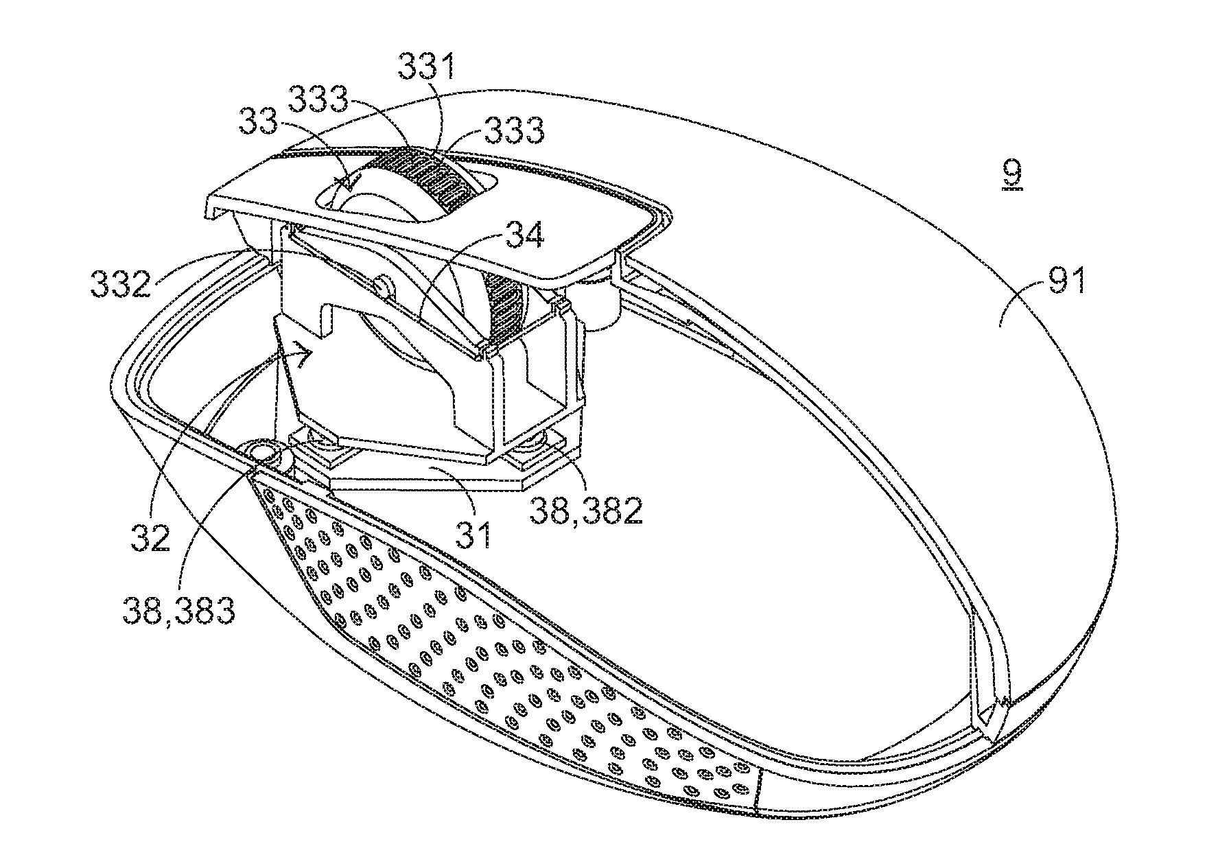
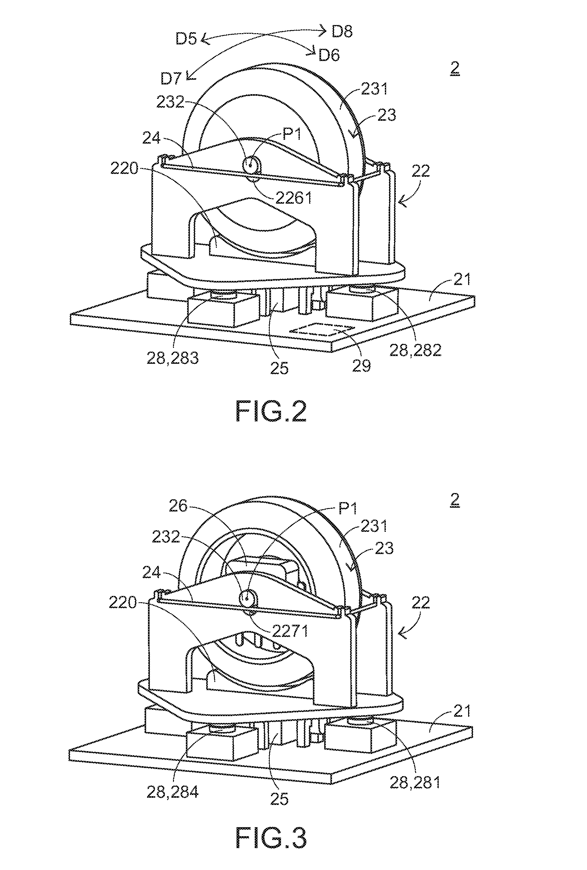
The present invention provides a roller module for an input device that can be operated with a single finger and can switch between different modes with a simple mode switching element. The module includes a mode switching element, a trigger sensing element, a circuit board, a wheel swinging element, a wheel sensing element, a micro control unit, and elastomers and switches for the wheel. The module can switch between a first working mode and a second working mode based on the mode switching element. The wheel swinging element can be moved upward and downward relative to the circuit board, and the wheel sensing element can generate a wheel signal when the wheel is moved. The elastomers provide a first elastic force to move the wheel upward, and the wheel sensing element generates a wheel signal when the wheel is moved. The micro control unit generates and outputs a first function command when the roller module is in the first working mode and a second function command when the roller module is in the second working mode. The wheel has an operation surface, and a friction piece is present to provide a better user experience. The trigger sensing element set includes four switches that control the image of a window on a computer screen. The elastomers have a larger elastic modulus than the first elastomer. The roller module allows for easy switching between different modes and application programs.

Problems solved by technology

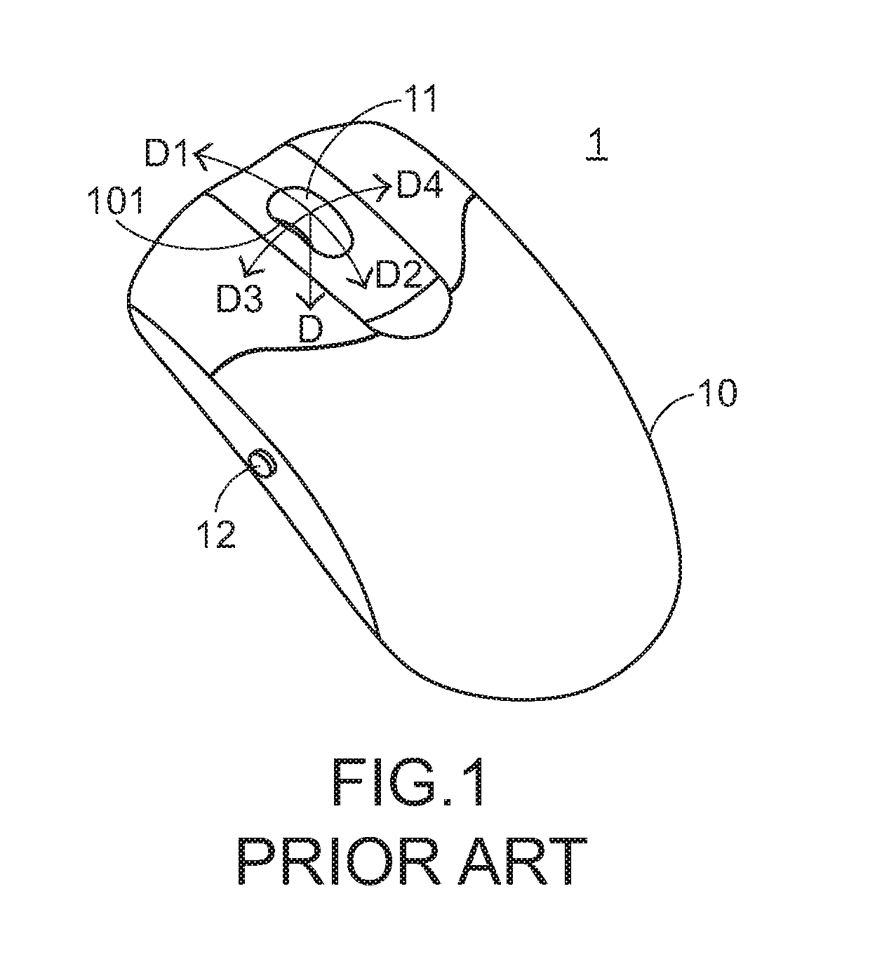
Such kind of mouse device only having the single rolling shaft is already difficult to satisfy the user with the usage of browsing the document file or the web page, and thus a mouse device with a tilting type wheel capable of shifting the image of the window on the computer screen in the horizontal direction is introduced.
As a result, the computer determines to process both of the first control command and the second control command after receives both of the first control signal and the second control signal at the same time, that results in an incorrect operation to the user, and such incorrect operation is considerable distress to the user.
In addition, with the professional software for the present computer becoming more diversified, the professional software can process much more functions, and the operation thereof consequently becomes more complicated.
Hence, the conventional mouse device 1 with the tilting type wheel 11 is difficult to satisfy the user's requirement due to it is only able to be rolled in the frontward / rearward direction and poked in the leftward / rightward direction.
As a result, the conventional mouse device with the tilting type wheel and arranged with the mode switching button is quite not easy to be operated by the user.

Method used


Image

  • Roller module for input device
  • Roller module for input device
  • Roller module for input device

Examples


Embodiment Construction

[0060]Reference will now be made in detail to specific embodiments of the present invention. Examples of these embodiments are illustrated in the accompanying drawings. While the invention will be described in conjunction with these specific embodiments, it will be understood that it is not intended to limit the invention to these embodiments. In fact, it is intended to cover alternatives, modifications, and equivalents as may be included within the spirit and scope of the invention as defined by the appended claims. In the following description, numerous specific details are set forth in order to provide a through understanding of the present invention. The present invention may be practiced without some or all of these specific details. In other instances, well-known process operations are not described in detail in order not to obscure the present invention.

[0061]The first thing to note is the present invention provides a roller module, the user is able to control a corresponding...


PUM


Abstract

The present invention discloses a roller module for an input device. The roller module includes a circuit board, a wheel swinging element arranged above the circuit board, a wheel arranged on the wheel swinging element, a mode switching element arranged between the circuit board and the wheel swinging element, a plurality of switches arranged between the circuit board and the wheel swinging element, and a micro control unit. When the wheel is moved downward a distance relative to the wheel swinging element, the wheel can't be rotated. When the wheel is pushed such that the wheel swinging element is tilted in a specific direction or moved downward, the corresponding one of the switches or the mode switching elements is triggered. When the mode switching element is triggered, the roller module is switched from a first working mode to a second working mode.

Description

FIELD OF THE INVENTION[0001]The present invention generally relates to a roller module, and more particularly to a roller module for an input device.BACKGROUND OF THE INVENTION[0002]With the rapid advancement of technology and the advents of the multimedia age and the computer age, the dependence of the people on various computer apparatuses is increased. As a result, various peripheral input devices for being the communications between the computer systems and the users, such as a mouse, a keyboard, a microphone and so on, play a vital role. Since the operation manner of the mouse device, which can be held by the user with his palm for controlling the movement of the mouse cursor and then the trajectory of the mouse cursor can be outputted on the computer screen, is so close to the using habit of the human being, the mouse device becomes the most common one of the peripheral input devices.[0003]In addition, it is usually necessary to scroll an image of a window on the computer scre...

Claims


Application Information

Patent Timeline
IPC IPC(8): G06F3/033
CPCG06F3/0338G06F3/0362G06F3/03543
Inventor PENG, CHUN-CHINGSU, CHUN-NAN
Owner PRIMAX ELECTRONICS LTD
Learn More