Laser working apparatus and method of controlling laser working apparatus

Active Publication Date: 2008-02-14
NISSAN MOTOR CO LTD
View PDF8 Cites 39 Cited by
  • Summary
  • Abstract
  • Description
  • Claims
  • Application Information

AI Technical Summary

Benefits of technology

[0010]Consequently, an object of the present invention is to provide a laser working apparatus that is easier to check a laser-beam target position at the time of checking instruction

Problems solved by technology

This has made it difficult to determine, in the test operation performed by the actual equipment, whether or not the robot and t

Method used


Image

  • Laser working apparatus and method of controlling laser working apparatus
  • Laser working apparatus and method of controlling laser working apparatus
  • Laser working apparatus and method of controlling laser working apparatus

Examples


Embodiment Construction

[0027]An embodiment to which the present invention is applied will be described in detail below with reference to the accompanying drawings.

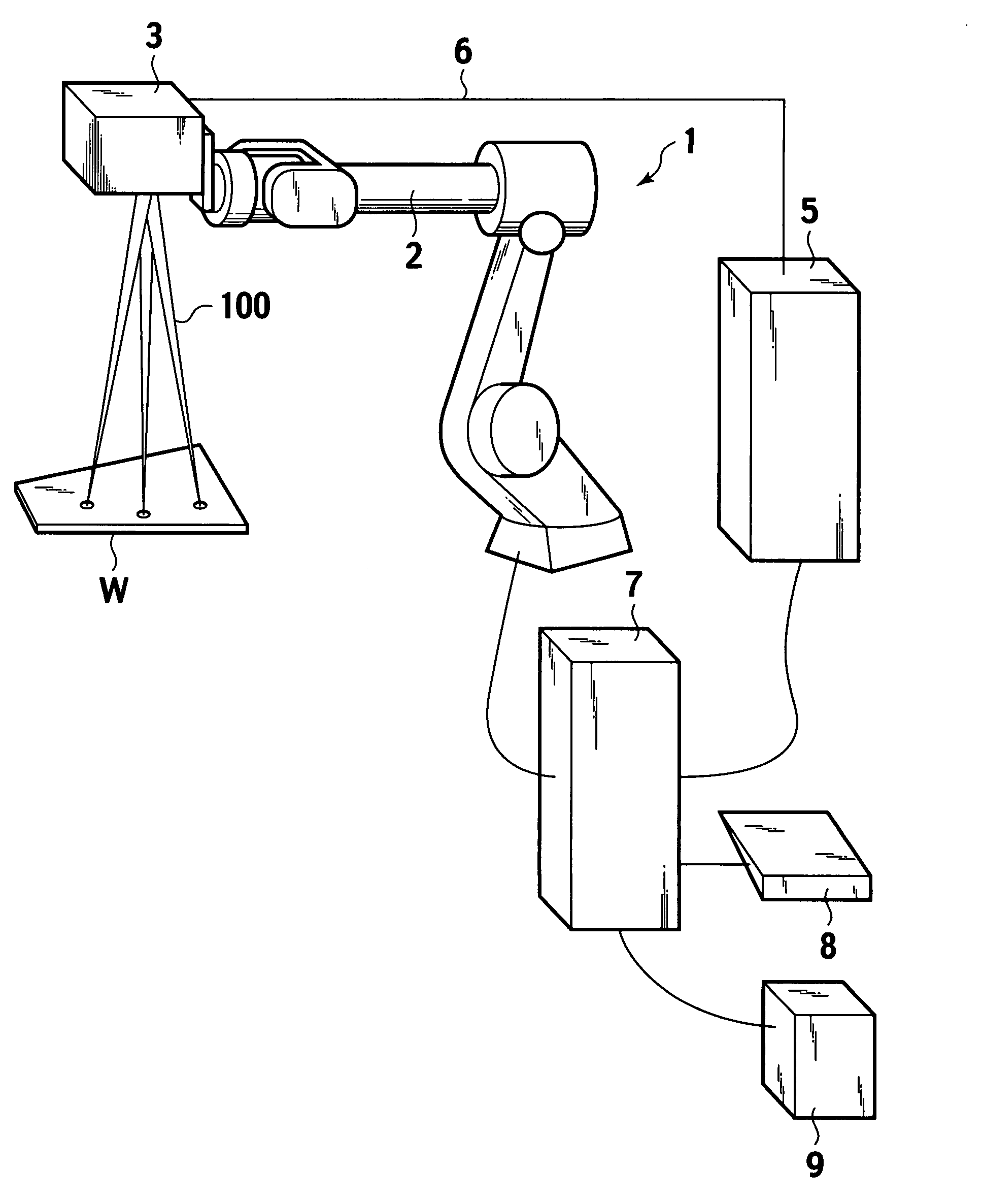
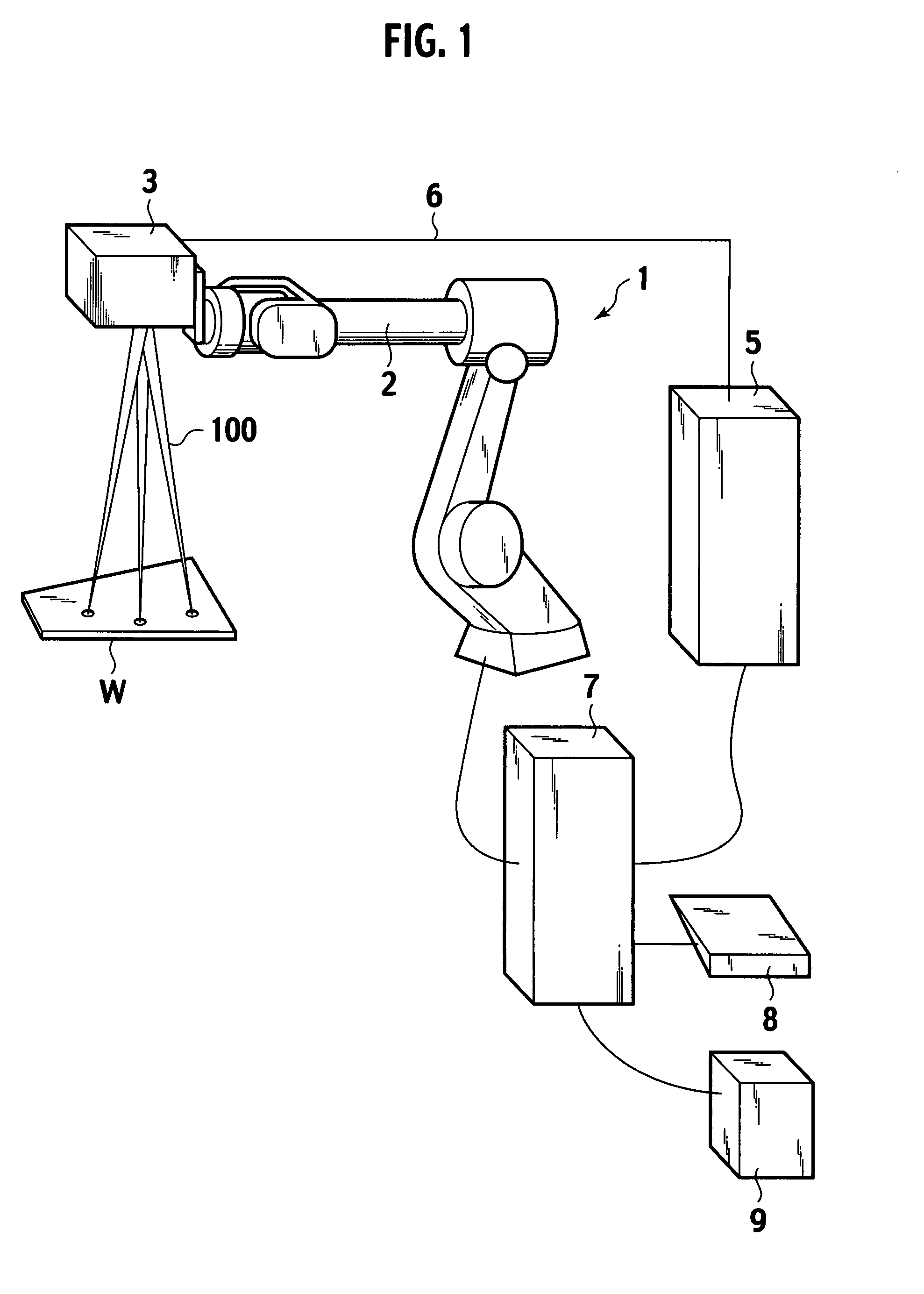
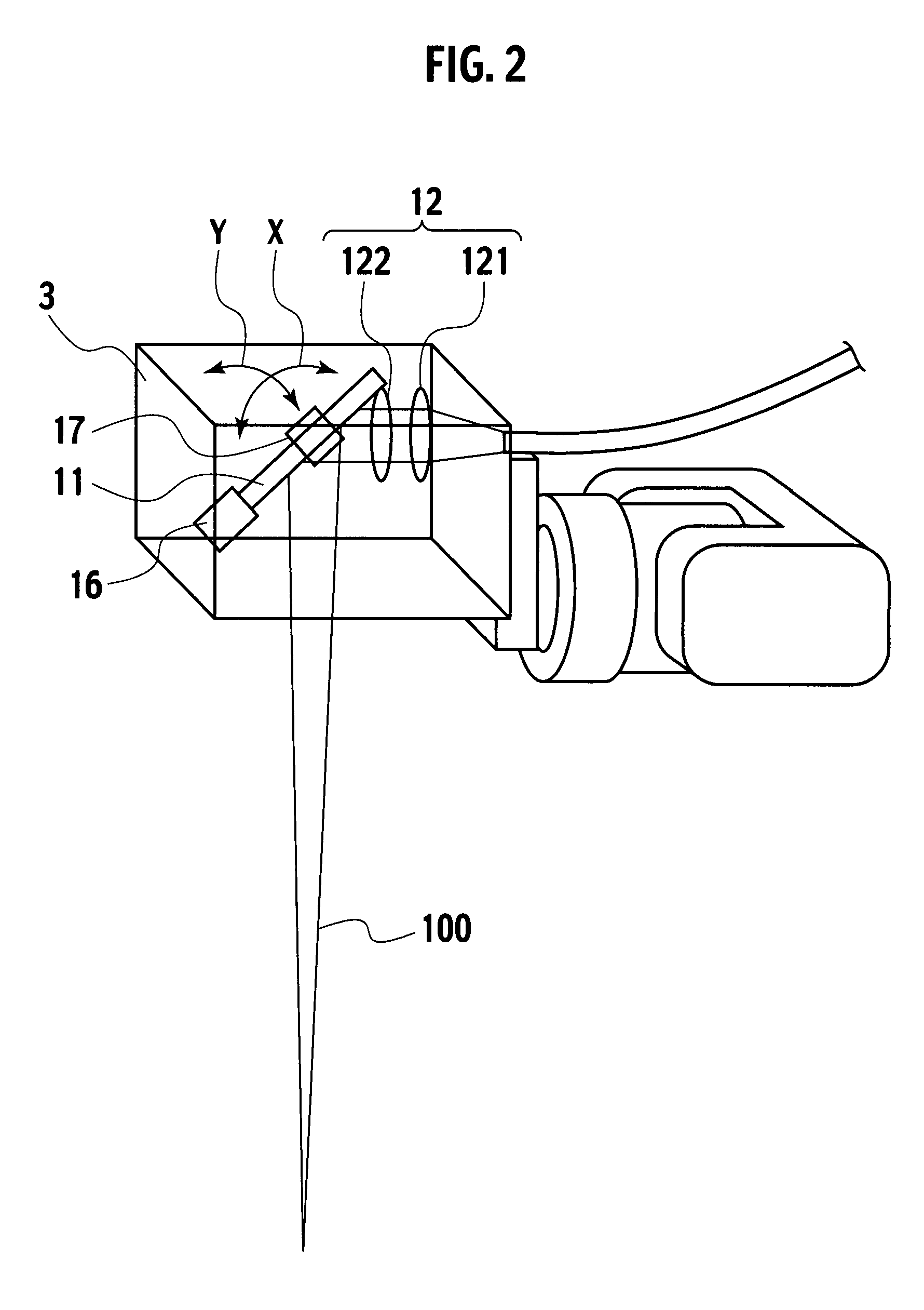
[0028]FIG. 1 is a schematic configuration diagram of a laser welding system to which the present invention is applied; FIG. 2 is an internal structure diagram of a laser emitting apparatus in the laser welding system; and FIG. 3 is an internal structure diagram of a laser oscillator in the laser welding system.

[0029]The laser welding system shown in FIG. 1 is configured to emit a laser beam 100 to a work piece W from a laser emitting apparatus 3 positioned above the work piece W, and thereby perform welding of the work piece W, which is a welded object provided as an object of the working, without coming in contact with the work piece W directly.

[0030]The illustrated laser welding system is composed of the following: a robot 1 (the mover); a laser emitting apparatus 3 (the laser emitter) which is attached to the extremity of an arm 2 of the robo...


PUM

PropertyMeasurementUnit
Timeaaaaaaaaaa

Abstract

Disclosed is a laser working apparatus including: a laser emitting apparatus provided with a reflector which changes the direction of any one of a laser beam and a visible light; a robot which moves the laser emitting apparatus; and a robot control apparatus which, when laser working is performed, controls the laser emitting apparatus so that the laser beam can draw a predetermined working pattern on the basis of a predetermined working position on a workpiece, and, when an operation checking work is performed, controls the laser emitting apparatus so that the visible light beam can be emitted only to a reference position of the working pattern.

Description

[0001]The present application is based on Japanese Patent Application No. 2006-221297, which was filed on Aug. 14, 2006 and the contents of the application is incorporated herein by reference and to which priority is claimed.[0002]1. Field of the Invention[0003]The present invention relates to a laser working apparatus and a method of controlling a laser working apparatus.[0004]2. Background of the Invention[0005]In recent years, laser working has come to be used in welding utilizing a robot. As a welding technique of this kind, a technique is known in which a predetermined welding point is welded with a laser emitting apparatus for emitting a laser beam being attached to the extremity of a robot arm (a manipulator) while a laser beam is moved by moving the robot arm and, at the same time, changing the direction of laser beam emitted from the laser emitting apparatus (for example, refer to Japanese Patent Application Laid-open Publication No. 2005-177862). The welding of this kind h...

Claims


Application Information

Patent Timeline
IPC IPC(8): B23K26/02B23K26/00B23K26/082B23K26/08
CPCB23K26/04B23K26/0884B25J9/1664B23K26/043G05B2219/40519G05B2219/45138B25J9/1671B23K26/359
Inventor HAMAGUCHI, YUJIYOSHIKAWA, NOBUHIRO
Owner NISSAN MOTOR CO LTD
Why Eureka
Try Eureka