Mounting rail and module latching system

a technology of mounting rails and latching systems, which is applied in the direction of couplings, rod connections, couplings, etc., can solve the problems of no additional electrical subassemblies can be mounted, no longer readily possible, and a lot of structural space, so as to facilitate the handling of the subassembly and the effect of simple separation

Inactive Publication Date: 2013-08-22
WEIDMULLER INTERFACE GMBH & CO KG
View PDF11 Cites 10 Cited by
  • Summary
  • Abstract
  • Description
  • Claims
  • Application Information

AI Technical Summary

Benefits of technology

[0035]In a further preferred embodiment, there is provided on the foot part a handle, in particular, for actuation by means of a screwdriver for the separation of the subassembly from the adjoining subassembly and / or from the mounting rail so that the operator will find it very simple to separate the subassembly by means of the handle.
[0036]To facilitate the handling of the subassembly during the arrangement and latching on the mounting rail, there is provided an edge for the attachment of the subassembly upon the mounting rail, preferably bilaterally on the mounting rail, and preferably two mounting rail latch means are to be arranged on the subassembly, each of which cooperates with one of the edges of the mounting rail. The mounting rail latch means here are preferably provided in such a manner that the subassembly first of all is arranged parallel to the subassembly in a position swung with respect to the mounting rail plane with one of the mounting rail latch means upon an edge of the mounting rail in order subsequently to swing it into the latch-on direction so that the other mounting rail latch means will be arranged on the other edge of the mounting rail. In a likewise preferred manner, the subassembly can be arranged upon the mounting rail in that it is arranged parallel to the subassembly plane as well as parallel to the mounting rail plane and in that it is shifted in the latch-on direction. The mounting rail latch means therefore avoid the edges likewise initially and they are then, on the basis of the force of the power means, pushed back against the shifting direction, whereby the subassembly is latched upon the mounting rail.

Problems solved by technology

But it takes a lot of structural space to push these units apart from each other so that there must be a longer part of the mounting rail for the mutual separation of the electrical subassemblies, which means that no additional electrical subassemblies can be mounted there.
The cancellation of parallelism and therefore an oblique separation of mutually adjoining electrical subassemblies from each other, however, depending on the particular model of the electrical contacts provided in mutually adjoining walls, for example, in the case of electrical contacts that are made in the form of plug and socket systems, is no longer readily possible.
This is because, depending on the structural shape of the contacts, there is the danger that the electrical contacts might be jammed against each other, causing short-circuits, or that the electrical contacts in the process might be damaged or even destroyed.

Method used


Image

  • Mounting rail and module latching system
  • Mounting rail and module latching system
  • Mounting rail and module latching system

Examples


Embodiment Construction

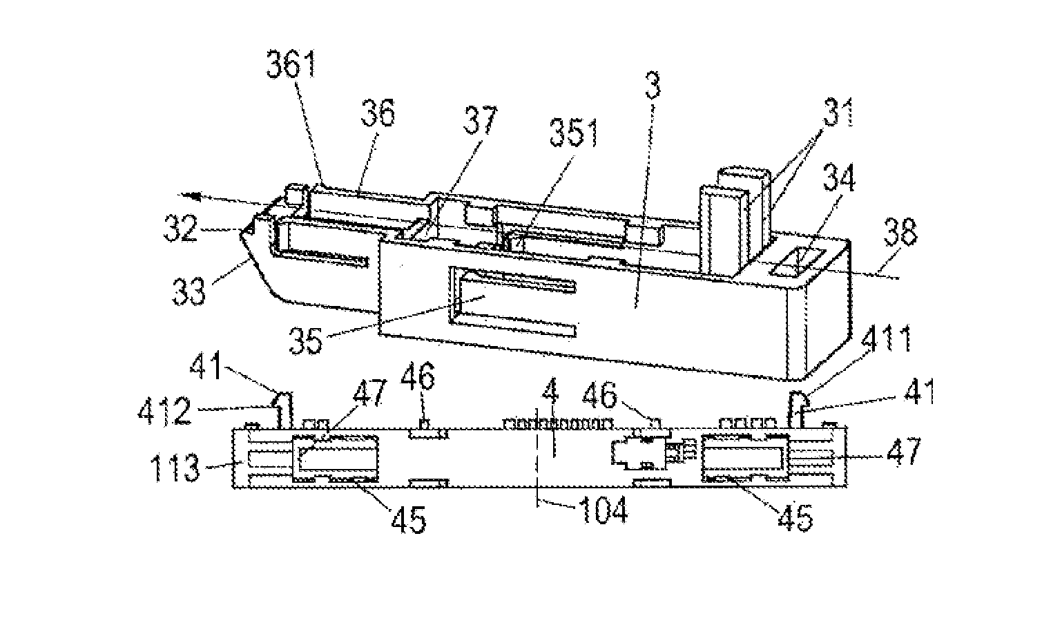
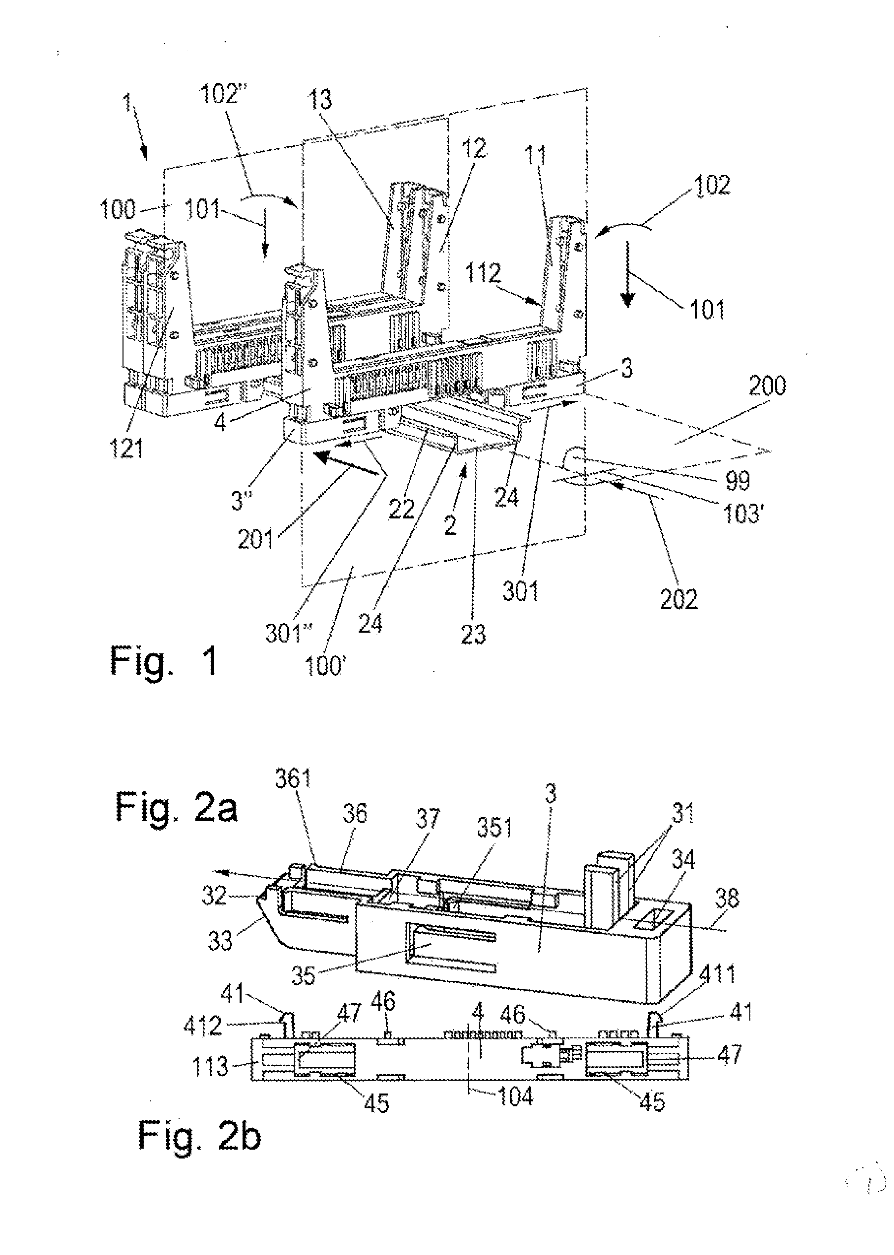
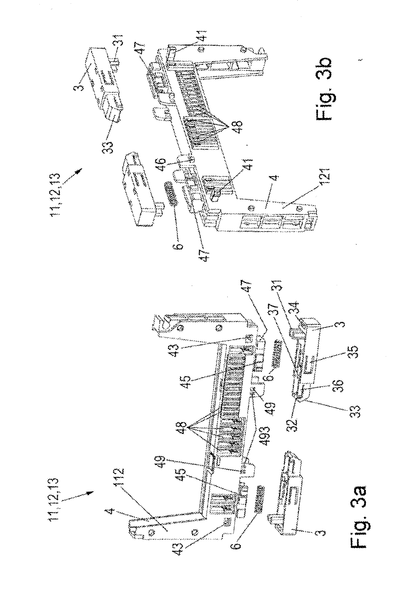
[0052]Referring first more particularly to FIG. 1, a plurality of module base members 11, 12 and 13 are arranged for mounting on a conventional top-hat type support rail 2 having a horizontal base portion 23, a pair of upwardly extending vertical leg portions 24, and a pair of outwardly extending flange portions 22. Connection block 1 comprises two mutually adjoining subassemblies 12, 13, which together are mounted on the support rail 2, as well as a subassembly 11, which is not yet mounted on the support rail.

[0053]Mounting rail 2 extends along a longitudinal axis 202 and has a U-shaped cross-section, with the flange portions 24 defining a horizontal mounting rail plane 200.

[0054]The adjoining subassembly arranged on mounting rail 2, which adjoins the subassembly 11 that is to be arranged on mounting rail 2, extends parallel to a subassembly plane 100. FIG. 1 further shows a second subassembly plane 100′ that is parallel to subassembly plane 100 in which extends the subassembly 11 ...


PUM


Abstract

A module latching arrangement for mounting and dismounting on a generally U-shaped support rail at least two module base bodies arranged orthogonally above and extending transversely across the support rail, each of the base bodies having a pair of bottom corner portions arranged on opposite sides of the support rail. At least one foot member is connected for horizontal longitudinal sliding movement relative to one of the base body corner portions relative to the adjacent support rail horizontal flange portion. A lateral displacement arrangement on the foot member is operable, when the foot member is displaced from a locked position toward an unlocked position relative to the support rail, to displace the first base body laterally away from an adjacent second base body mounted on the support rail. The foot member is latched in either a locked or an unlocked position relative to the base member.

Description

REFERENCE TO RELATED APPLICATIONS[0001]This application is a national stage application under 35 U.S.C. §371 of PCT International Application No. PCT / EP2011 / 063420 filed Aug. 4, 2011, claiming priority of German application No. 20 2010 008 319.2 filed Aug. 20, 2010.BACKGROUND OF THE INVENTION[0002]1. Field of the Invention[0003]A module latching arrangement for mounting and dismounting on a generally U-shaped support rail at least two module base bodies arranged orthogonally above and extending transversely across the support rail, a foot member being connected with a first base body for horizontal longitudinal sliding movement between locked and unlocked positions relative to the adjacent support rail horizontal flange portion. A lateral displacement arrangement on the foot member is operable, when the foot member is displaced from a locked position toward an unlocked position relative to the support rail, to displace the first base body laterally away from an adjacent second base ...

Claims


Application Information

Patent Timeline
Patent Type & Authority Applications(United States)
IPC IPC(8): H02B1/052
CPCH01R9/2608H01R13/633H02B1/041Y10T403/7075H02B1/0523H02B1/308H02B1/052
Inventor SCHUMACHER, RALFWOHLGEMUTH, KLAUSFEHLING, STEPHANKULTURIDI, GEORGNIGGEMANN, MATTHIASPUESCHNER, KLAUSWALDHOFF, MARCO
Owner WEIDMULLER INTERFACE GMBH & CO KG
Why Eureka
Try Eureka