Antenna element as capacitive proximity/touch sensor for adaptive antenna performance improvement

Active Publication Date: 2013-08-22
GOOGLE TECH HLDG LLC
View PDF10 Cites 107 Cited by
  • Summary
  • Abstract
  • Description
  • Claims
  • Application Information

AI Technical Summary

Problems solved by technology

Even within larger sized wireless communications and/or processing devices, it is becoming difficult to find space for a separate capacitive proximity sensor for multiple antennas (e.g., the various antennas employed for 2G/3G/4G).
In fact, one of the reasons antennas in a wireless communication have narrow bandwidth is due to lack of

Method used


Image

  • Antenna element as capacitive proximity/touch sensor for adaptive antenna performance improvement
  • Antenna element as capacitive proximity/touch sensor for adaptive antenna performance improvement
  • Antenna element as capacitive proximity/touch sensor for adaptive antenna performance improvement

Examples


second embodiment

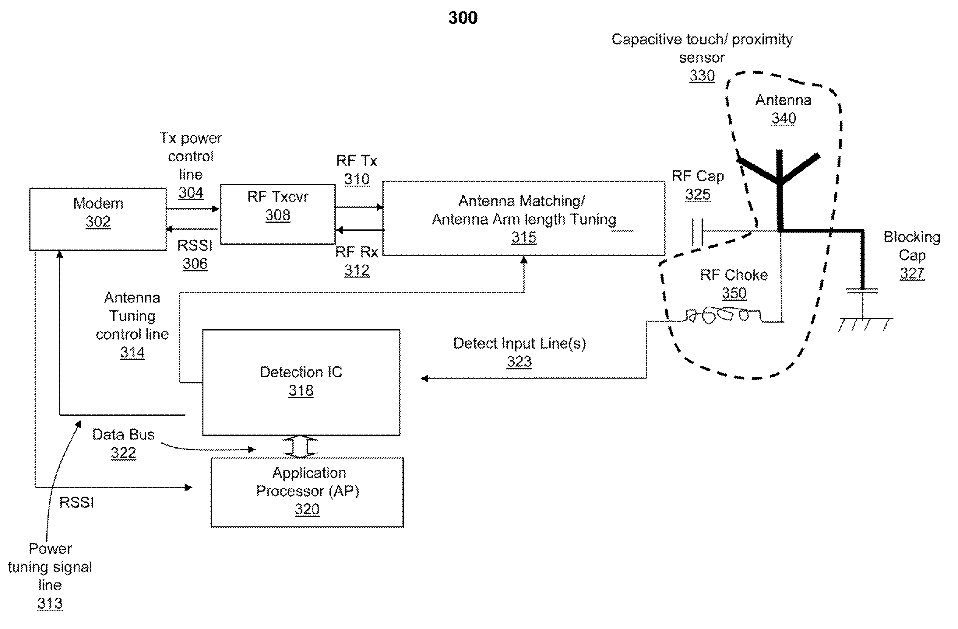
[0039]FIG. 3 illustrates a block diagram representation of RFCCs, including a CTPS, in a WCD, according to a RFCC 300 illustrates a second configuration from among several configurations that are presented herein. RFCC 300 comprises AMTC 315 coupled to an output of RF transceiver 308. RFCC 300 also comprises antenna element 340 coupled to an output of AMTC 315 by coupling capacitor 325. Antenna element 340 is RF shorted to ground using a low frequency blocking capacitor 327. Antenna element 340 is further coupled to at least one RF choke 350. Antenna element 340 and RF choke 350 collectively function to provide CTPS 330. Also included within RFCC 300 is detection IC 318 that is coupled to RF choke 350 of CTPS 330. RFCC 300 also includes modem 302 that is coupled to RF transceiver 308. RF transceiver 308 forwards / provides, to modem 302, a RSSI that provides information about RF signal power detected at antenna element 340. Additionally, RFCC 300 comprises AP 320 that is connected by...

third embodiment

[0041]FIG. 4 illustrates a block diagram representation of radio frequency communications components (RFCC), including a capacitive touch and proximity sensor, in a wireless communications device (WCD), according to a RFCC 400 illustrates a third configuration from among the several configurations that are presented herein. RFCC 400 comprises AMTC 415 coupled to an output of RF transceiver 408. RFCC 400 also comprises antenna element 440 coupled to an output of AMTC 415 by coupling capacitor 425. Antenna element 440 is RF shorted to ground using a low frequency blocking capacitor 427. Antenna element 440 is further coupled to at least one RF choke 450. Antenna element 340 and RF choke 350 collectively function to provide CTPS 330. Also included within RFCC 400 is detection IC 418 that is coupled to RF choke 450 of CTPS 430. RFCC 400 also includes modem 402 that is coupled to RF transceiver 408. RF transceiver 408 forwards / provides, to modem 402, a RSSI that provides information abo...

fourth embodiment

[0043]FIG. 5 illustrates a block diagram representation of RFCCs, including a CTPS, in a WCD, according to a RFCC 500 comprises AMTC 515 coupled to an output of RF transceiver 508. RFCC 500 also comprises antenna element 540 coupled to an output of AMTC 515 by coupling capacitor 525. Antenna element 540 is RF shorted to ground using a low frequency blocking capacitor 527. Antenna element 540 is further coupled to at least one RF choke 550. Antenna element 340 and RF choke 350 collectively function to provide CTPS 330. Also included within RFCC 500 is detection IC 518 that is coupled to RF choke 550 of CTPS 530. RFCC 500 also includes modem 502 that is coupled to RF transceiver 508. RF transceiver 508 forwards / provides, to modem 502, a RSSI that provides information about RF signal power detected at antenna element 540. Additionally, RFCC 500 comprises AP 520 that is connected by data bus 522 to detection IC 518. In addition, AP 520 is coupled to an output signal port of modem 502. ...


PUM


Abstract

A method and communications device for providing antenna tuning to compensate for antenna de-tuning caused by a presence of an object detected using an antenna element within a capacitive touch and proximity sensor (CTPS). The CTPS propagates object detection signals associated with a detected object to a detection IC. An object detection and antenna tuning (ODAT) logic uses object detection signal information to generate tuning control signals to trigger compensatory antenna tuning, based on pre-established mappings of object detection signal data and antenna tuning states. The tuning control signals indicate at least one of (a) a level of compensatory antenna impedance tuning and (b) an amount of compensatory antenna length adjustment. In response to generating the tuning control signals, the ODAT logic triggers the propagation of the tuning control signals to the antenna matching and control circuit to provide the corresponding antenna tuning.

Description

BACKGROUND[0001]1. Technical Field[0002]The present disclosure relates in general to communication devices and in particular to object detection and antenna tuning in communication devices.[0003]2. Description of the Related Art[0004]In many wireless communication devices, traditional approaches to object detection are implemented. For example, Transmit Power Reduction is a commonly applied technique that is used to mitigate Near Field Electromagnetic Energy Exposure when an object comes into close proximity to a transmit antenna in the wireless communication device. The level of Transmit Power Reduction is based upon determining whether object contact or proximity occurs close to the antenna elements of the wireless communication device. One of the approaches for object detection is to employ a “separate” capacitive proximity sensor “near” the antenna element to detect presence of a body / object and then to reduce transmit power.[0005]One of the mechanisms by which the antenna perfo...

Claims


Application Information

Patent Timeline
IPC IPC(8): H04B1/40H04W52/04
CPCH01Q1/243H03K17/962H03K17/955H01Q1/52H01Q1/245
Inventor ABDUL-GAFFOOR, MOHAMMED R.BREUNIG, BRIANLI, QIUMINGMEHROTRA, AKSHAT
Owner GOOGLE TECH HLDG LLC
Why Eureka
Try Eureka