

Single circuit multiple spray cone pressure atomizers
- Summary
- Abstract
- Description
- Claims
- Application Information
AI Technical Summary
Benefits of technology
Problems solved by technology
Method used
Image

Examples
Embodiment Construction
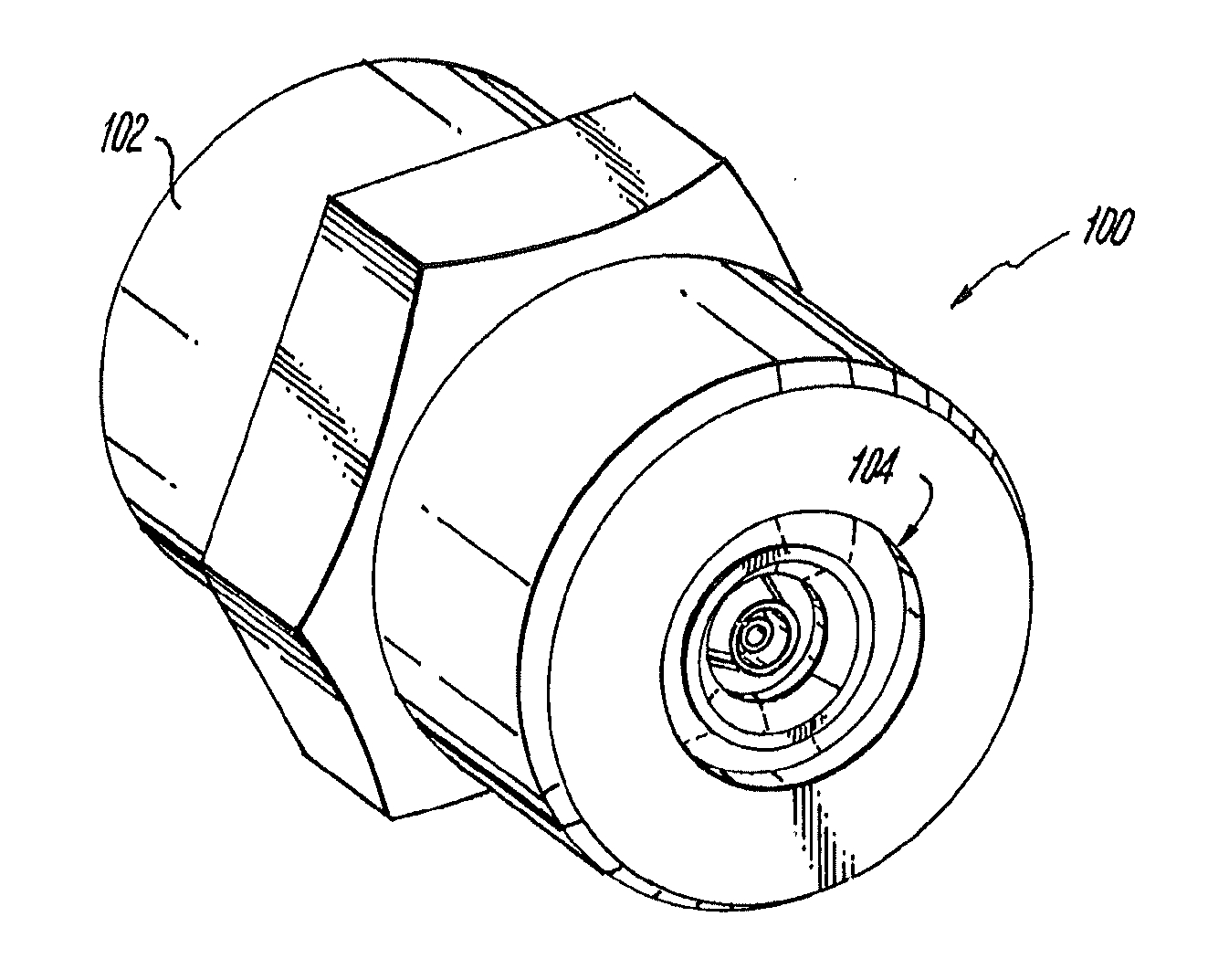
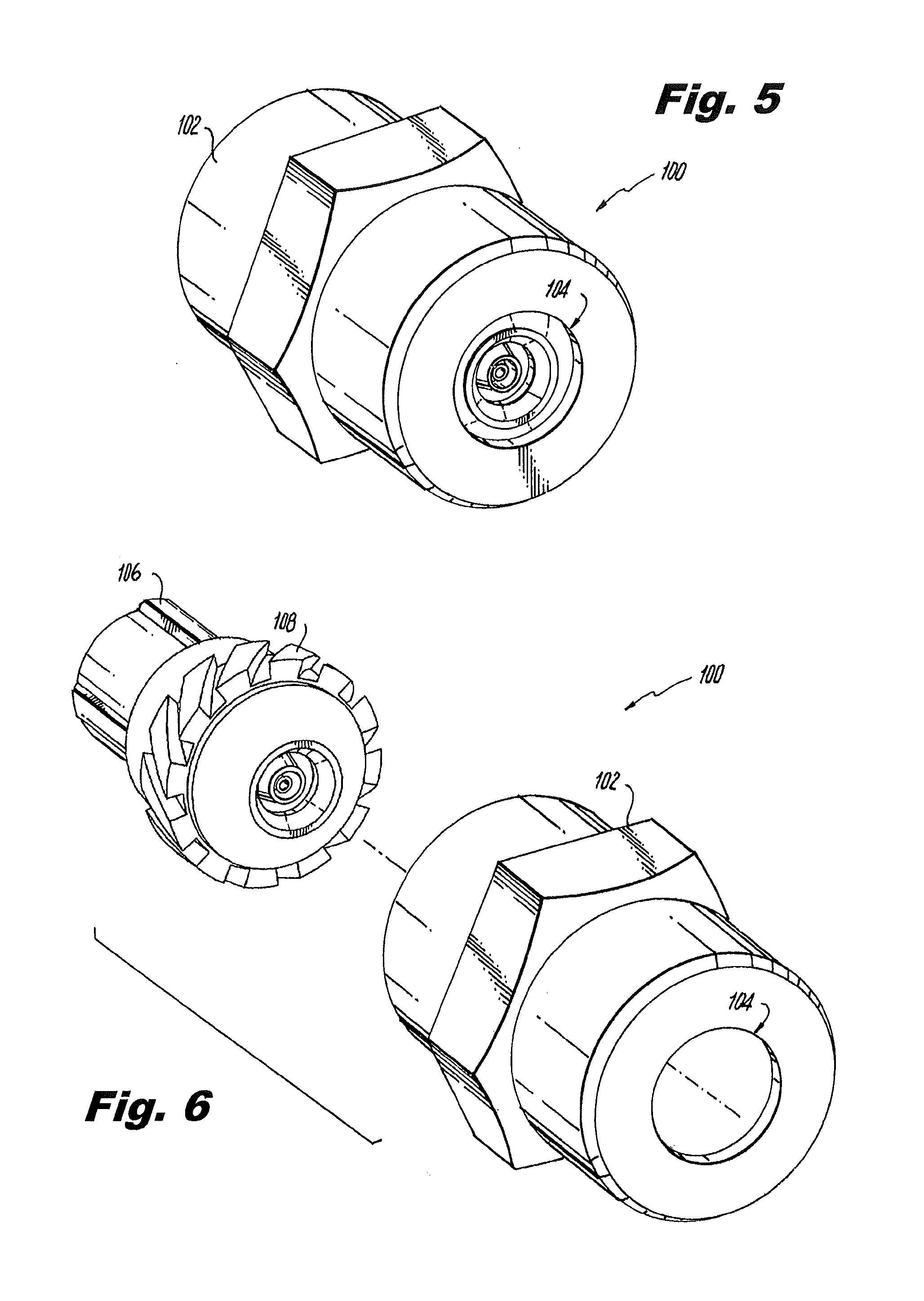
[0036]Reference will now be made to the drawings wherein like reference numerals identify similar structural features or aspects of the subject invention. For purposes of explanation and illustration, and not limitation, a partial view of an exemplary embodiment of an atomizer in accordance with the invention is shown in FIG. 5 and is designated generally by reference character 100. Other embodiments of atomizers in accordance with the invention, or aspects thereof, are provided in FIGS. 6-20, as will be described. The systems of the invention can be used to produce atomized sprays of liquid with a substantially solid spray cones over a range of pressures.
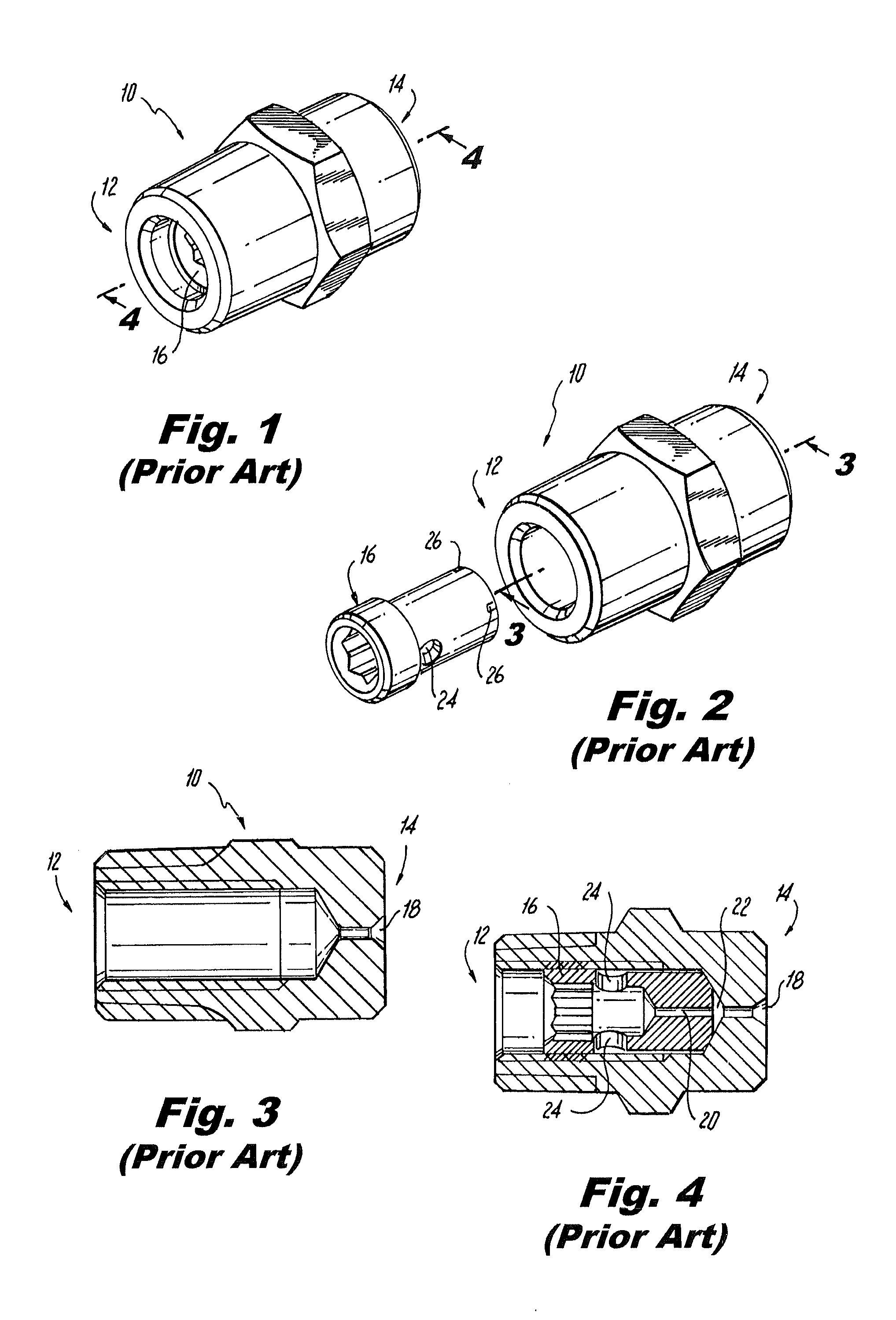
[0037]With reference first to FIG. 1, a pressure atomizer 10 of the prior art is shown having an inlet end 12 and an outlet end 14. A core 16, shown separately in FIG. 2, divides the flow internally to produce a solid spray cone. Outlet end 14 includes a single outlet orifice 18, shown in FIG. 3, which is fed from two sources. Firs...
PUM
 Abstract
Description
Claims
Application Information