
Paper feed apparatus, image forming apparatus, and paper feed method

Inactive Publication Date: 2013-08-29
KYOCERA DOCUMENT SOLUTIONS INC
View PDF4 Cites 4 Cited by
  • Summary
  • Abstract
  • Description
  • Claims
  • Application Information

AI Technical Summary

Benefits of technology

The present patent is about a paper feed apparatus, image forming apparatus, and method that improves productivity by shortening the waiting time for paper feeding. The apparatus is able to lift the bottom plate to position the paper stack at the ready-to-feed position, thus allowing for more efficient paper feeding and reduced waiting time. This lifting process improves productivity by speeding up the paper feeding process.

Problems solved by technology

Consequently, there is a problem in that a time taken to form (print) an image is lengthened by a waiting time and hence productivity is degraded.
In particular, when paper is fed while switching between a plurality of paper housing units (paper feed stages) is performed, there is a problem in that productivity is significantly degraded because the above-described waiting time occurs every time the paper feed stage is switched.
Thus, when the paper housing unit has been pulled out for paper supply or the like, the loss of paper in pressure contact with the pickup roller, the deformation of the pickup roller, or the like is likely to occur.

Method used


Image

  • Paper feed apparatus, image forming apparatus, and paper feed method
  • Paper feed apparatus, image forming apparatus, and paper feed method
  • Paper feed apparatus, image forming apparatus, and paper feed method

Examples


Embodiment Construction

[0023]Hereinafter, details of a paper feed apparatus and an image forming apparatus in accordance with an embodiment of the present disclosure will be described with reference to the drawings. Hereinafter, an example in which the image forming apparatus is a composite device will be described.

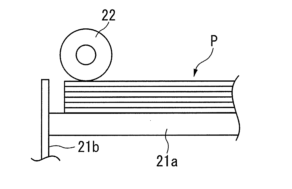
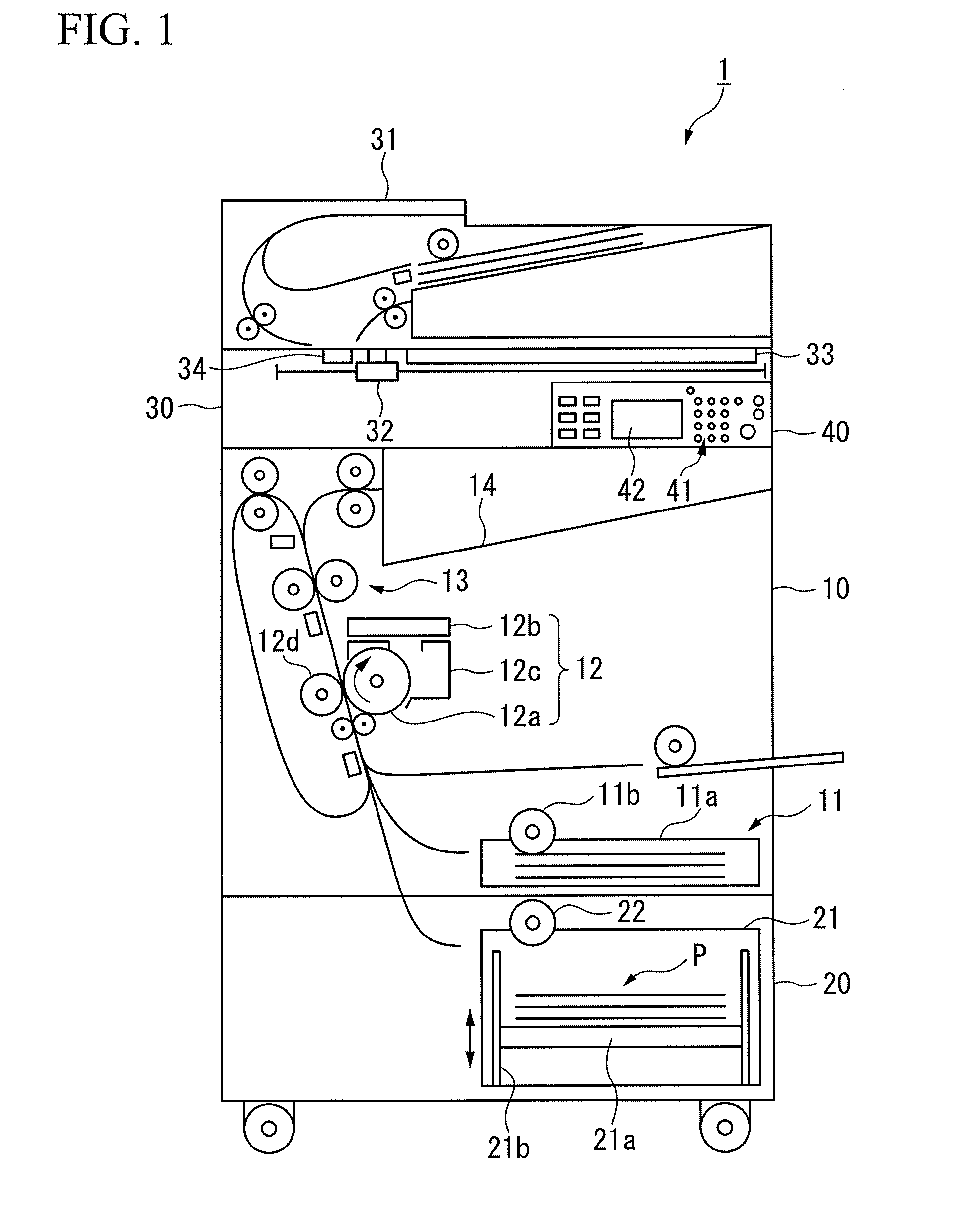
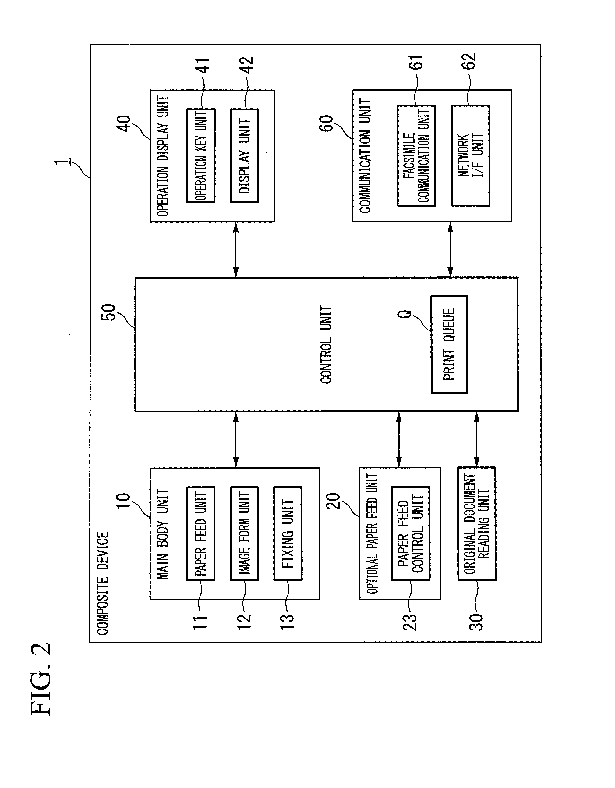
[0024]FIG. 1 is a front perspective view illustrating a configuration of main parts of the composite device as the image forming apparatus in accordance with the embodiment of the present disclosure. As illustrated in FIG. 1, the composite device 1 includes a main body unit 10, an optional paper feed unit 20 (a paper feed apparatus), an original document reading unit 30, an operation display unit 40, and the like. The composite device 1 has a copy function, a print function, a facsimile transmission / reception function, and the like.

[0025]The main body unit 10 includes a paper feed unit 11, an image form unit 12, a fixing unit 13, a paper discharge tray 14, and the like. The main body unit 10 pr...


PUM


Abstract

A paper feed apparatus includes a paper housing unit configured to house paper at a first position, a bottom plate provided in the paper housing unit and configured to retain the paper, a moving unit configured to move the bottom plate between the first position and a second position, a paper feed roller configured to feed the paper retained by the bottom plate at the second position, and a paper feed control unit configured to cause the moving unit to move the bottom plate to the second position when a paper feed preparation request for requesting paper feed preparation has been input.

Description

BACKGROUND OF THE DISCLOSURE[0001]This application is based upon and claims the benefit of priority from prior Japanese Patent Application No. 2012-044102, filed Feb. 29, 2012, the entire contents of which are incorporated herein.FIELD OF THE DISCLOSURE[0002]The present disclosure relates to a paper feed apparatus, an image forming apparatus, and a paper feed method.DESCRIPTION OF RELATED ART[0003]Image forming apparatuses such as a printer, a copier, and a composite device form an image on paper by carrying a toner image of an image to be formed on an image carrier such as a photoconductive drum and transferring the toner image to the paper (print paper) to fix the transferred image thereon. Thus, the image forming apparatus includes a paper feed apparatus, which feeds paper housed in a paper housing unit sheet by sheet every time the tonner image is carried by the image carrier.[0004]The paper feed apparatus lifts a bottom plate (a plate that retains a paper stack housed in the pa...

Claims


Application Information

Patent Timeline
IPC IPC(8): G03G15/00
CPCG03G15/6511G03G15/6529
Inventor YAMAGUCHI, KIYOTAKA
Owner KYOCERA DOCUMENT SOLUTIONS INC
Learn More