Capless filler neck

a filler neck and capless technology, applied in the field of capless filler necks, can solve the problems of users already or still trying to fill fuel, and achieve the effect of optimizing the opening tim

Active Publication Date: 2013-09-05
GERDES
View PDF5 Cites 17 Cited by
  • Summary
  • Abstract
  • Description
  • Claims
  • Application Information

AI Technical Summary

Benefits of technology

[0020]The opposite, free end of the lever then projects in the direction of the neck axis and into the path of movement of the fuel nozzle, so that the inserted fuel nozzle presses the lever downwards. With a suitable arrangement and length of the lever, the latter then pushes with its free end onto the pressure surface of the lower closure flap and pushes the latter open, as already described above in connection with the upper closure flap. Here, also, the geometry of the lever and of the lower closure flap can optimize the opening times.

Problems solved by technology

The disadvantage of the known filler necks can consist in that already when the filler pipe is only partially inserted or after filling the tank when the filler pipe is already partially withdrawn, the user already or still attempts to fill fuel in.
This leads to the fuel being able to arrive into the environment via the venting systems, which is not desirable for ecological reasons.

Method used


Image

  • Capless filler neck
  • Capless filler neck
  • Capless filler neck

Examples


Embodiment Construction

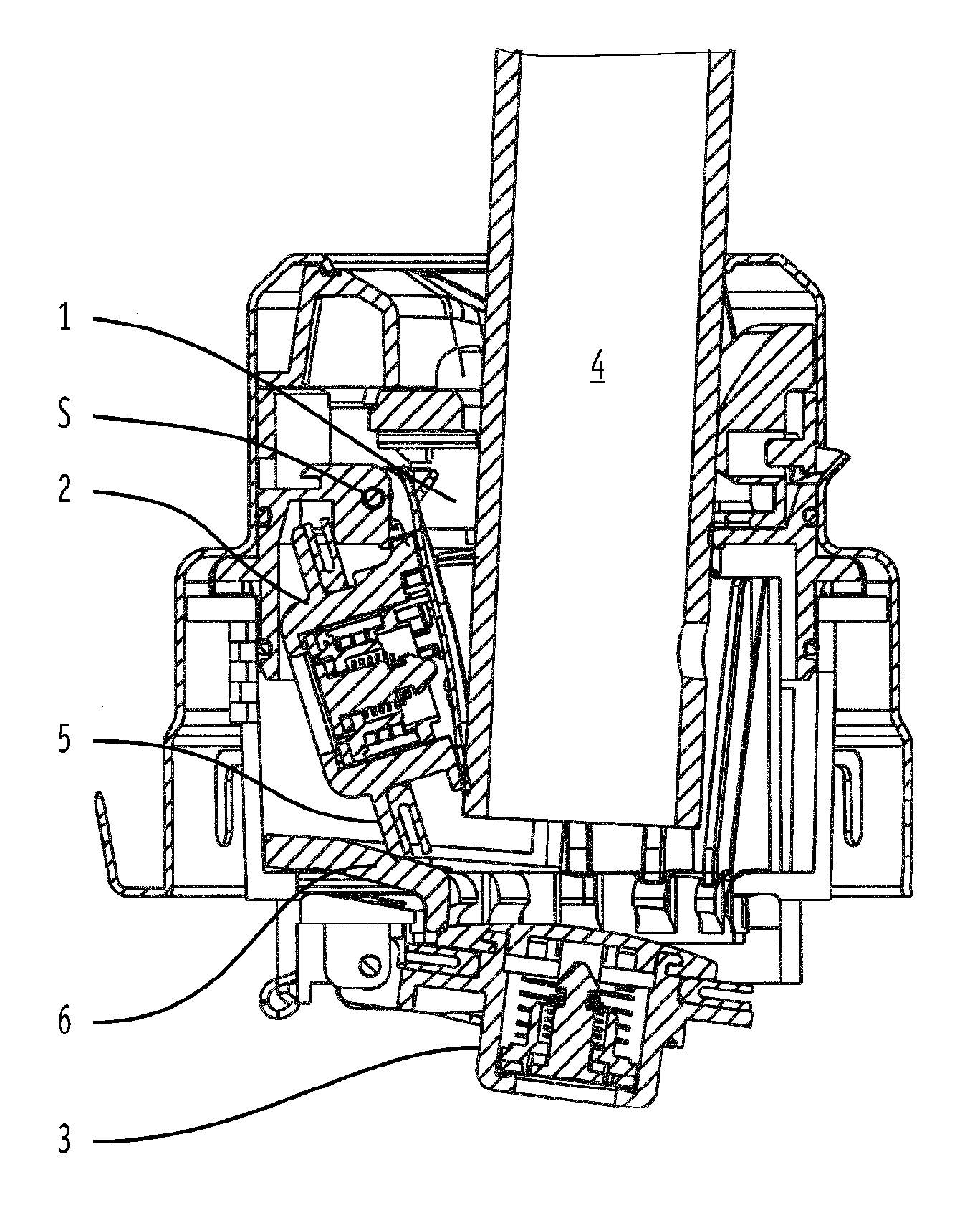
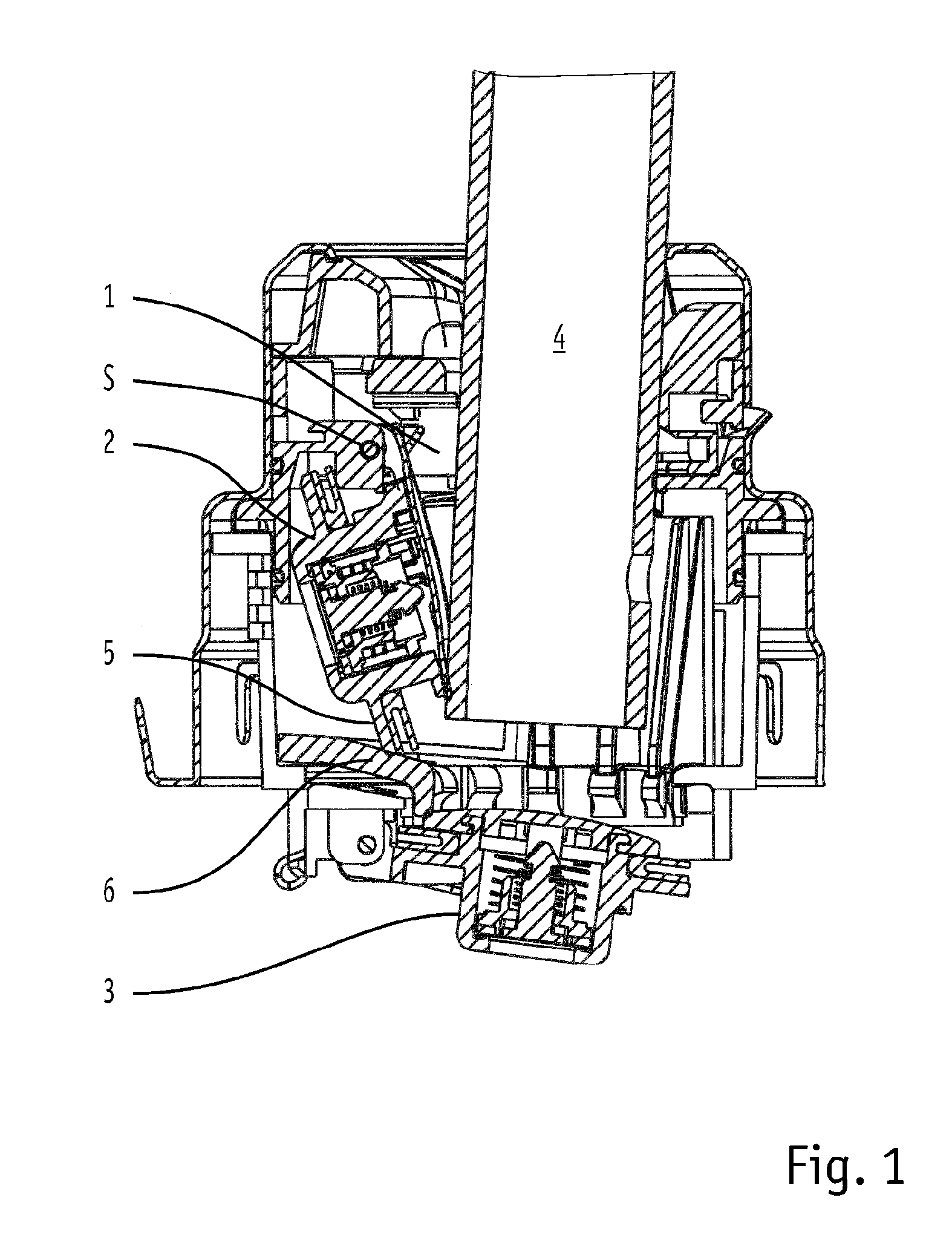
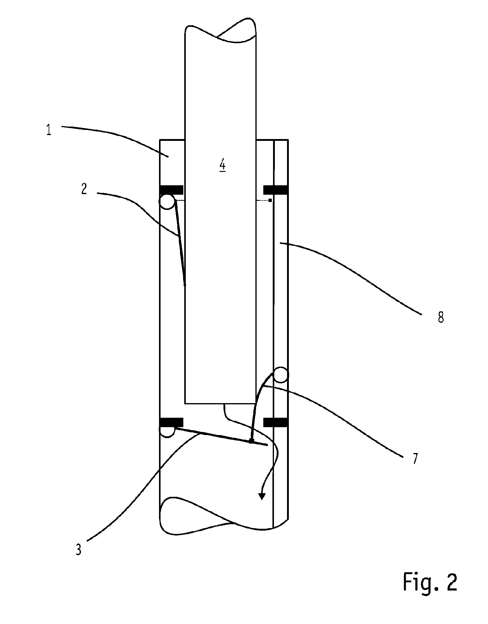
[0026]The neck end has in the upper region of its pipe section 1 an introduction funnel for the insertion of the filler pipe 4 of a fuel nozzle. The upper closure flap 2 is provided therebeneath. This upper closure flap 2 is swivellably mounted about a swivel axis S and can be pushed open by the introduced fuel nozzle. In the lower region, the upper closure flap 2 has a flange bearing a seal.

[0027]The flange of the closure flap 2 moves with its edge facing away from the swivel axis S along a circular path. This movement line initially runs in a circular shape from a lateral position starting from above downwards about the swivel axis S. After a first angle section of the movement line, a first swivelling path is passed through, whilst the upper closure flap 2 is not yet in contact with the lower closure flap 3. This ensures that both flaps 2, 3 operate independently of one another and both can respectively seal the neck.

[0028]The upper closure flap 2 only abuts against the upper sid...


PUM

PropertyMeasurementUnit
pressureaaaaaaaaaa
distanceaaaaaaaaaa
widthaaaaaaaaaa

Abstract

The invention relates to a capless filler neck having an upper closure flap 2 and a lower closure flap 3, which are arranged in a pipe section 1. The two closure flaps 2, 3 must be able to seal independently of one another. In known capless filler necks, this has the effect that, when the filler pipe 4 of a fuel nozzle is still partially inserted, the lower closure flap 3 is already closed, whereas the user still has the impression that tank filling can be carried out. As a result, fuel collects between the two closure flaps 2, 3.
The invention prevents this in that the lower closure flap 3 is opened or held open by the upper closure flap 2 or by an actuating element even when the filler pipe 4 is no longer in contact with the lower closure flap 2.

Description

TECHNICAL FIELD[0001]The invention relates to a capless filler neck with delayed-closing closure flap for a neck of a container, in particular of a tank of a motor vehicle with a pipe section running along a neck axis and with a closure mechanism, which has an upper closure flap and a lower closure flap arranged therebeneath, wherein at least the lower closure flap is constructed as a sealing flap and the upper closure flap and the lower closure flap are able to be pushed open by the insertion of a filler pipe into the pipe section against a restoring force for opening the closure mechanism.PRIOR ART[0002]Capless filler necks with delayed-closing closure flap of this kind are known from WO 2009 / 135954 A (GERDES GMBH) 12.11.2009. These are filler necks which securely close with the two closure flaps the filler neck of a fuel tank even without a separate tank cap. The two closure flaps are pushed open here by the pipe end of a fuel nozzle or of a refill can, hereinafter designated gen...

Claims


Application Information

Patent Timeline
Patent Type & Authority Applications(United States)
IPC IPC(8): B60K15/04
CPCB60K15/0406B60K2015/0461B60K2015/0429B60K15/04
Inventor GERDES, RALF
Owner GERDES
Why Eureka
Try Eureka