Buoy camera shooting control system and method

A technology of a control system and a control method, applied in the field of ocean observation and detection, can solve the problems of energy waste and high structural cost, and achieve the effects of reducing power consumption and power consumption

Inactive Publication Date: 2019-09-13
QINGDAO NAT LAB FOR MARINE SCI & TECH DEV CENT
View PDF8 Cites 5 Cited by
  • Summary
  • Abstract
  • Description
  • Claims
  • Application Information

AI Technical Summary

Problems solved by technology

[0004] The shooting function of the buoy is mainly used when a collision occurs or a suspicious target appears. The camera with low power consumption in the above-mentioned patent only prolongs the working time of the camera on the basis of the same energy, and it still works when there is no need to shoot. It brings about a great waste of energy; adopting the method of setting a power supply device for the buoy not only brings about the problem of high structural cost, but also causes a waste of energy

Method used


Image

  • Buoy camera shooting control system and method
  • Buoy camera shooting control system and method
  • Buoy camera shooting control system and method

Examples


Embodiment Construction

[0035] In the following, the present invention will be specifically described through exemplary embodiments. It should be understood, however, that elements, structures and characteristics of one embodiment may be beneficially incorporated in other embodiments without further recitation.

[0036] In the description of the present invention, it should be noted that unless otherwise specified and limited, the terms "installation", "connection" and "connection" should be understood in a broad sense, for example, it can be a fixed connection or a detachable connection. Connected, or integrally connected; it can be directly connected, or indirectly connected through an intermediary, and it can be the internal communication of two elements. Those of ordinary skill in the art can understand the specific meanings of the above terms in the present invention in specific situations.

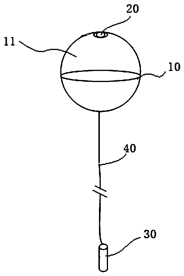
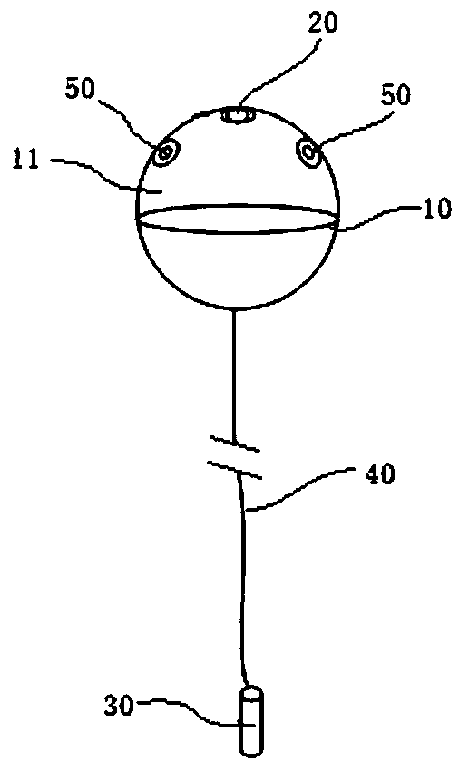
[0037] The present invention is aimed at the problem that the small and medium-sized buoys in the prior...


PUM


Abstract

The invention provides a buoy camera shooting control system and method, and belongs to the technical field of ocean observation and detection. The buoy camera shooting control system comprises a buoybody, and a camera arranged in the buoy body, and an underwater sound monitoring device used for monitoring a sea area sound signal in real time, and a main control unit arranged in the buoy body. The underwater acoustic monitoring device is connected with the buoy body, and the main control unit is electrically connected with the camera and the underwater acoustic monitoring device and used forcontrolling the camera to be turned on and off according to an acoustic signal monitored by the underwater acoustic monitoring device. The buoy camera shooting control method comprises the following steps: the main control unit controlling the camera on the buoy body to be turned on and off according to an acoustic signal monitored by the underwater acoustic monitoring device. Under the conditionof limited energy and power consumption, the system not only has a real-time monitoring function, but also can intelligently control the opening and closing of a photographing or video recording function.

Description

technical field [0001] The invention belongs to the technical field of ocean observation and detection, and in particular relates to a buoy camera control system and method. Background technique [0002] At present, with regard to ocean observation and detection, basically only cable equipment or large-scale observation equipment have the functions of real-time monitoring, photographing and video recording; the existing small uncable floating platforms, such as small The reason is that monitoring, photographing and video recording cannot be carried out, resulting in the inability to detect abnormal targets in real time, and unable to take photographs or videos in real time when a collision occurs or other suspicious targets appear. [0003] Chinese utility model patent CN205652289U discloses a marine monitoring buoy, including a buoy, a serial port camera is installed on the outside of the buoy, and the serial port camera is serially connected with a data acquisition device,...

Claims


Application Information

Patent Timeline
Patent Type & Authority Applications(China)
IPC IPC(8): H04N7/18H04N5/232B63B22/00G01C13/00
CPCH04N7/188B63B22/00G01C13/00B63B2022/006H04N23/60
Inventor 李春乾唐军武张成伦史景文张立新柴瀛卢泽宇彭利军
Owner QINGDAO NAT LAB FOR MARINE SCI & TECH DEV CENT
Why Eureka
Try Eureka