Common focus energy emitter

Active Publication Date: 2013-09-05
NETA
View PDF1 Cites 19 Cited by
  • Summary
  • Abstract
  • Description
  • Claims
  • Application Information

AI Technical Summary

Benefits of technology

[0015]Common focus energy emitters of the present invention can be packaged as discrete replaceable components for use in more complex devices and systems. Energy emitters of the present invention can be packaged as discrete energy emitting devices including a controller for controlling the energy emitter. Controllers can be pre-programmed or user programmable. Such energy emitting devices can include one or more sensors for sensing ambient conditions for controlling their operation. E...

Problems solved by technology

However, since nearly all the rays emitted by the energy sources are not on the imaginary plane, so correspondingly the aforesaid refle...

Method used


Image

  • Common focus energy emitter
  • Common focus energy emitter
  • Common focus energy emitter

Examples


Embodiment Construction

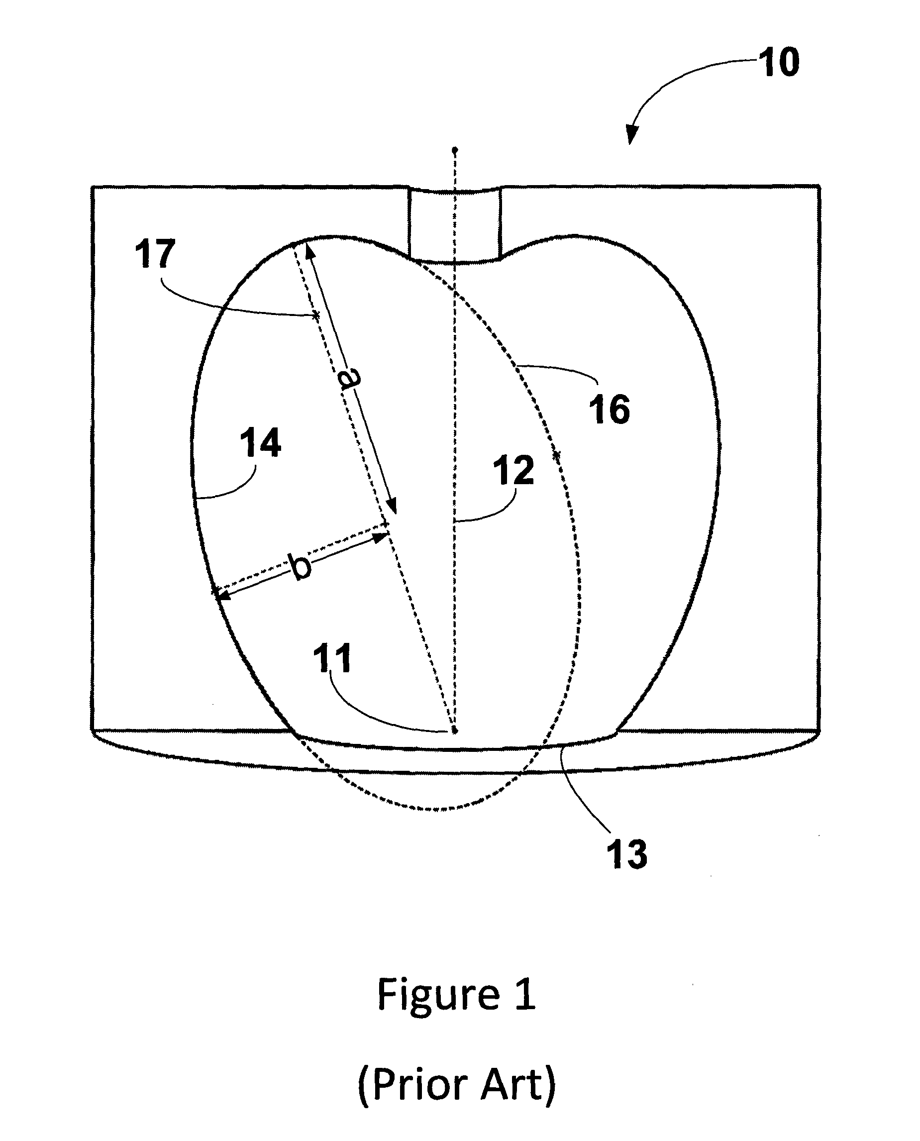
[0041]FIGS. 1 to 3 show a prior art three dimensional concave reflector 10 having a common focal point 11, a reflector axis 12 and an exit beam aperture 13 as illustrated and described in aforementioned U.S. Pat. No. 4,089,047 to Luderitz and U.S. Pat. No. 4,754,381 to Downs. The concave reflector 10 is constructed by revolution of a partial elliptical shape 14 of an imaginary ellipse 16 about the reflector axis 12. The imaginary ellipse 16 has a second focal point 17, a semi-major axis a and a semi-minor axis b in an imaginary plane including the reflector axis 12. The vast majority of rays radiating from a light source deployed in the concave reflector 10 do not lie on an imaginary plane including the reflector axis 12 such that the concave reflector 10 can focus only a very small proportion of the total available energy emitted by the light source along the exit beam axis.

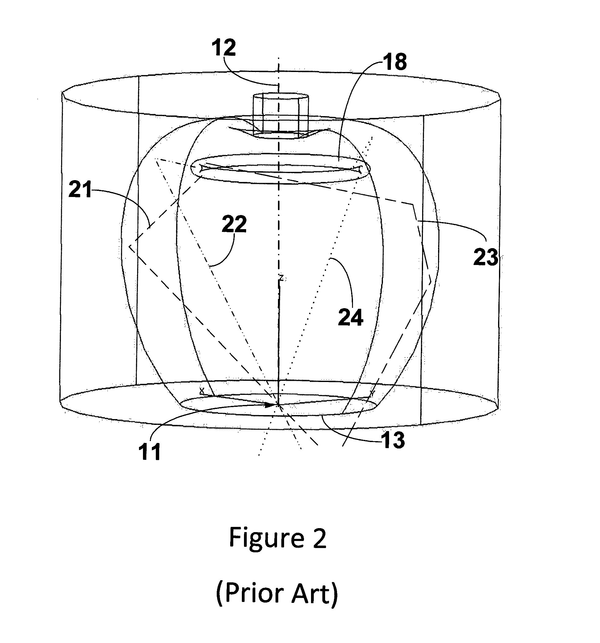
[0042]FIGS. 2 and 3 show the concave reflector 10 having a ring light source 18 for outwardly radiating light...


PUM


Abstract

The invention is directed towards common focus energy emitters having a common focus energy source and including two or more energy source units each having a 3D concave primary reflector for reflecting energy into an energy beam focused at the common focus energy source, and a secondary optical element for shaping the energy beam into an exit beam component of the exit beam. The 3D concave primary reflectors bound a minor 3D concave section of an imaginary primary reflector ellipsoid of revolution having a primary reflector axis of revolution non-coaxial with the energy emitter axis. Each primary reflector axis of revolution includes a first focal point disposed at the common focus energy source and a second focal point where its associated energy source is disposed thereat.

Description

FIELD OF THE INVENTION[0001]The invention pertains to common focus energy emitters for emitting an exit beam toward an object.BACKGROUND OF THE INVENTION[0002]Common focus energy emitters are known in the art.[0003]U.S. Pat. No. 4,089,047 to Luderitz illustrates and describes three dimensional concave compound reflectors for focusing light from two or more light sources into an exit light beam.[0004]U.S. Pat. No. 4,754,381 to Downs illustrates and describes three dimensional ellipsoidal concave reflector systems for the concentration of light, ultrasonic or shock waves, and the like, into an exit beam.[0005]The aforesaid reflectors have a partial elliptical shape in an imaginary plane including an exit beam axis defined between a common focus energy source and an exit beam aperture. The aforesaid reflectors bound an imaginary body of revolution formed by revolution of the partial elliptical shape about the energy emitter axis. However, since nearly all the rays emitted by the energy...

Claims


Application Information

Patent Timeline
IPC IPC(8): F21V7/08F21V13/04G03B15/03F21V14/04
CPCF21V7/0033F21V7/06F21V7/08F21V13/04F21V14/04F21V7/0058F21Y2101/025F21Y2113/002G03B15/03G03B2215/0582G03B2215/0596F21Y2101/02F21Y2115/30F21Y2113/10F21Y2115/10G03B2215/05
Inventor NETA
Owner NETA
Why Eureka
Try Eureka