Projection image displaying device

a projection image and display device technology, applied in the field of projection image displaying devices, can solve the problems of reducing the life of the light source, and achieve the effect of stable display performance and deterioration of the luminance of the projected imag

Active Publication Date: 2013-09-12
MAXELL HLDG LTD
View PDF1 Cites 8 Cited by
  • Summary
  • Abstract
  • Description
  • Claims
  • Application Information

AI Technical Summary

Benefits of technology

[0012]According to the present invention, deterioration of the luminance of the projected image caused by the dust adhering to the reflective surface of the p

Problems solved by technology

Since excessive temperature rise reduces the life of the light source and causes deformation of the display device and image

Method used


Image

  • Projection image displaying device
  • Projection image displaying device
  • Projection image displaying device

Examples


embodiment 1

Embodiment 1

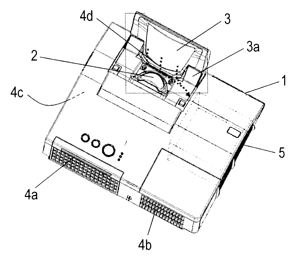
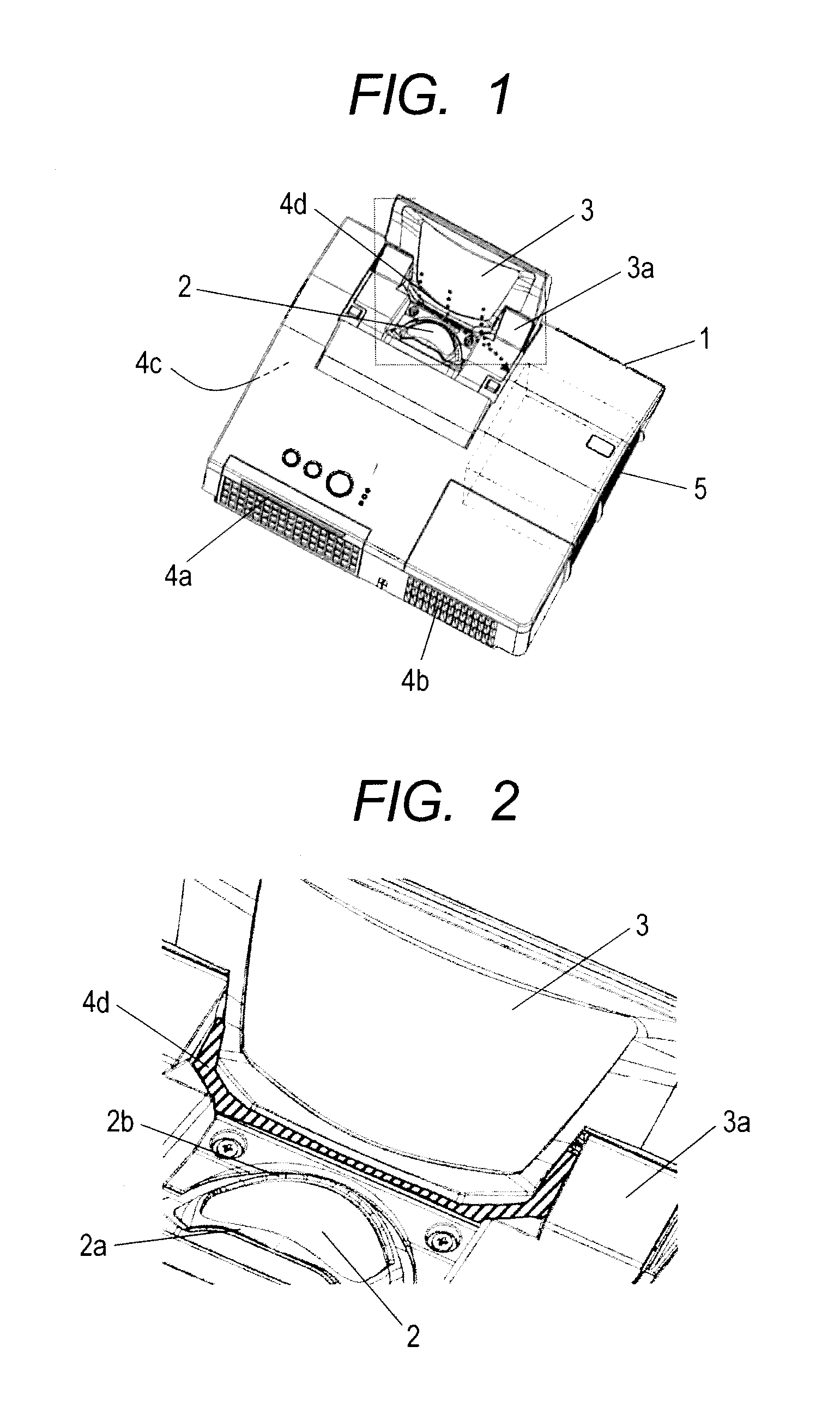
[0027]FIG. 1 is an outline view showing one embodiment of a projection image displaying device. FIG. 2 is an enlarged diagram of the vicinity of a projection mirror of the projection image displaying device in FIG. 1.

[0028]The configuration of the projection image displaying device is such that it has a sealable projection mirror 3 on an upper surface of a case 1, and imaging light emitted from a projection lens 2 is enlarged and projected onto a projecting plane such as a screen or the like by being reflected by a projection mirror 3. Although optical components such as a light source, a display device (a liquid crystal panel) and others are contained within the inside of the case 1, external air is taken in through air inlets 4a to 4d by a cooling fan and air after cooling is discharged through an exhaust port 5 in order to cool heat generated components. While the air inlets 4a and 4b are provided on the front surface side of the case and the air inlet 4c is provided ...

embodiment 2

Embodiment 2

[0048]In the embodiment 1, the structure that adhesion of the dust and the like to the projection mirror is prevented while using the projection image displaying device in a state where the projection mirror is unsealed has been described. On the other hand, in the embodiment 2, a structure that adhesion of the dust and the like to the projection mirror is greatly reduced while using the projection image displaying device in a state where the projection mirror is sealed will be described.

[0049]FIG. 11 is an outline view showing a state where the projection mirror of the projection image displaying device used in the embodiment 1 is sealed. In the mirror sealing type projection image displaying device, when the power source is turned off, lighting of the light source is turned off to perform an operation of sealing the projection mirror 3. However, a cooling operation is performed for a predetermined time in order to cool heat generated components within the device. In th...


PUM


Abstract

In a projection image displaying device which projects imaging light emitted from a projection lens 2 by being reflected by a projection mirror 3, an air inlet 4d for sucking external air is provided at the position of a sealing mechanism 3a of the projection mirror 3. Air blown off through openings 2a, 2b provided around the projection lens 2 is sucked into a case through this air inlet 4d. When a cooling operation of cooling components within the case is to be performed by sealing the projection mirror 3, a sucking operation through the air inlet 4d is stopped. This prevents dust in the external air from adhering to a reflective surface of the projection mirror regardless of the installation state of the projection image displaying device.

Description

TECHNICAL FIELD[0001]The present invention relates to a projection image displaying device.BACKGROUND ART[0002]In a projection image displaying device such as a liquid crystal projector or the like, a short projection displaying device in which a projection mirror (a reflection mirror) for folding an optical path is provided between a projection lens and a projecting plane (such as a screen or the like) to reduce the distance between it and the projecting plane is marketed. In addition, in installation modes of the projection image displaying device, various installation modes are possible depending on the application such as not only floor installation that it is installed on a desk or the like, but also suspended installation that it is suspended from a ceiling, upward projection installation that projection is performed toward a ceiling or the like, downward projection installation that projection is performed toward a desk or the like and others.[0003]In these projection image d...

Claims


Application Information

Patent Timeline
IPC IPC(8): G03B21/16
CPCG03B21/28G03B21/16G02B21/28
Inventor HIRATA, KOJIFUKUI, MASAYUKIONO, CHOHEISAITO, HIDEHARUKATAYAMA, TAKESHI
Owner MAXELL HLDG LTD
Why Eureka
Try Eureka