Turbine airfoil with an internal cooling system having vortex forming turbulators

a technology of vortex-forming turbulators and turbine airfoils, which is applied in the direction of blade accessories, machines/engines, mechanical apparatuses, etc., can solve problems such as the likelihood of failure, achieve the effects of reducing heat transfer augmentation, dispersing boundary layers of cooling fluids, and high internal convective heat transfer ra

Inactive Publication Date: 2013-09-12
SIEMENS ENERGY INC
View PDF2 Cites 17 Cited by
  • Summary
  • Abstract
  • Description
  • Claims
  • Application Information

AI Technical Summary

Benefits of technology

[0008]During use, the cooling fluids may be passed into the cooling channel. The upstream corner of the center turbulator trips the boundary layer and creates turbulence. The turbulent cooling fluids form a vortex downstream of the turbulator that rolls along the length of the turbulator. However, the vortex rolls downstream and away from the turbulator by the incoming cooling fluids flowing over the turbulator. As the vortices propagate along the full length of the downstream side of center turbulators, the boundary layer becomes progressively more disturbed or thickened, but the outer turbulators disrupt such boundary layer formation, thereby preventing boundary layer growth that significantly reduces heat transfer augmentation. The vortex continues to increase in diameter as the vortex rolls away from the turbulator. The vortex may be disrupted by a downstream outer turbulator positioned downstream and radially outward from the center turbulator. The sets of center and outer turbulators effectively dissipate boundary layers of cooling fluids in cooling channels in industrial gas turbine engines. This unique vortex turbulator cooling arrangement formed by the sets of center and outer turbulators creates higher internal convective cooling potential for the turbine blade cooling channel, thus generating a high rate of internal convective heat transfer and efficient overall cooling system performance. This performance equates to a reduction in cooling demand and better turbine engine performance.
[0009]An advantage of this invention is that the turbine airfoil cooling system is configured to cool cooling channels and because of its configuration is particularly well suited to cool cooling channels in industrial gas turbine engines. These and other embodiments are described in more detail below.

Problems solved by technology

In addition, turbine vanes and blades often contain cooling systems for prolonging the life of the vanes and blades and reducing the likelihood of failure as a result of excessive temperatures.

Method used


Image

  • Turbine airfoil with an internal cooling system having vortex forming turbulators
  • Turbine airfoil with an internal cooling system having vortex forming turbulators
  • Turbine airfoil with an internal cooling system having vortex forming turbulators

Examples


Embodiment Construction

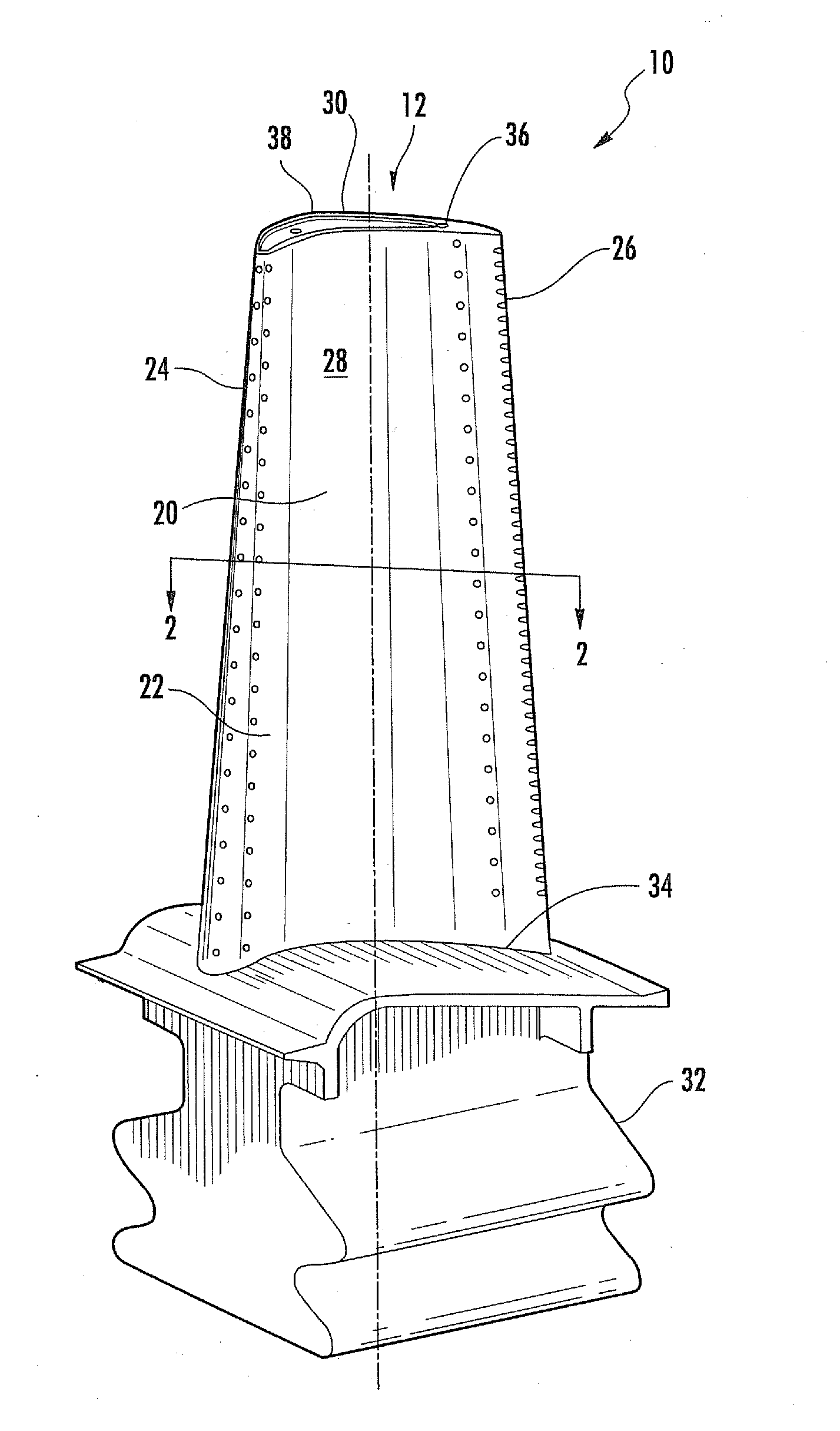
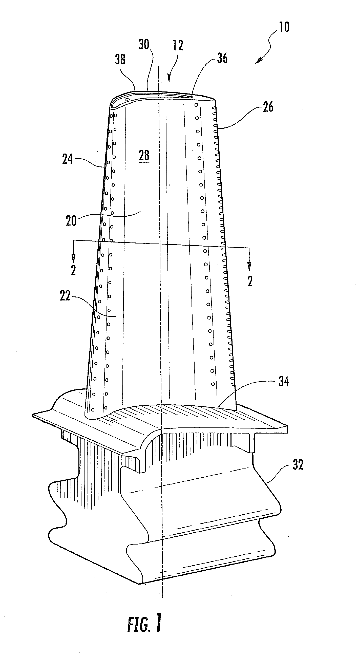
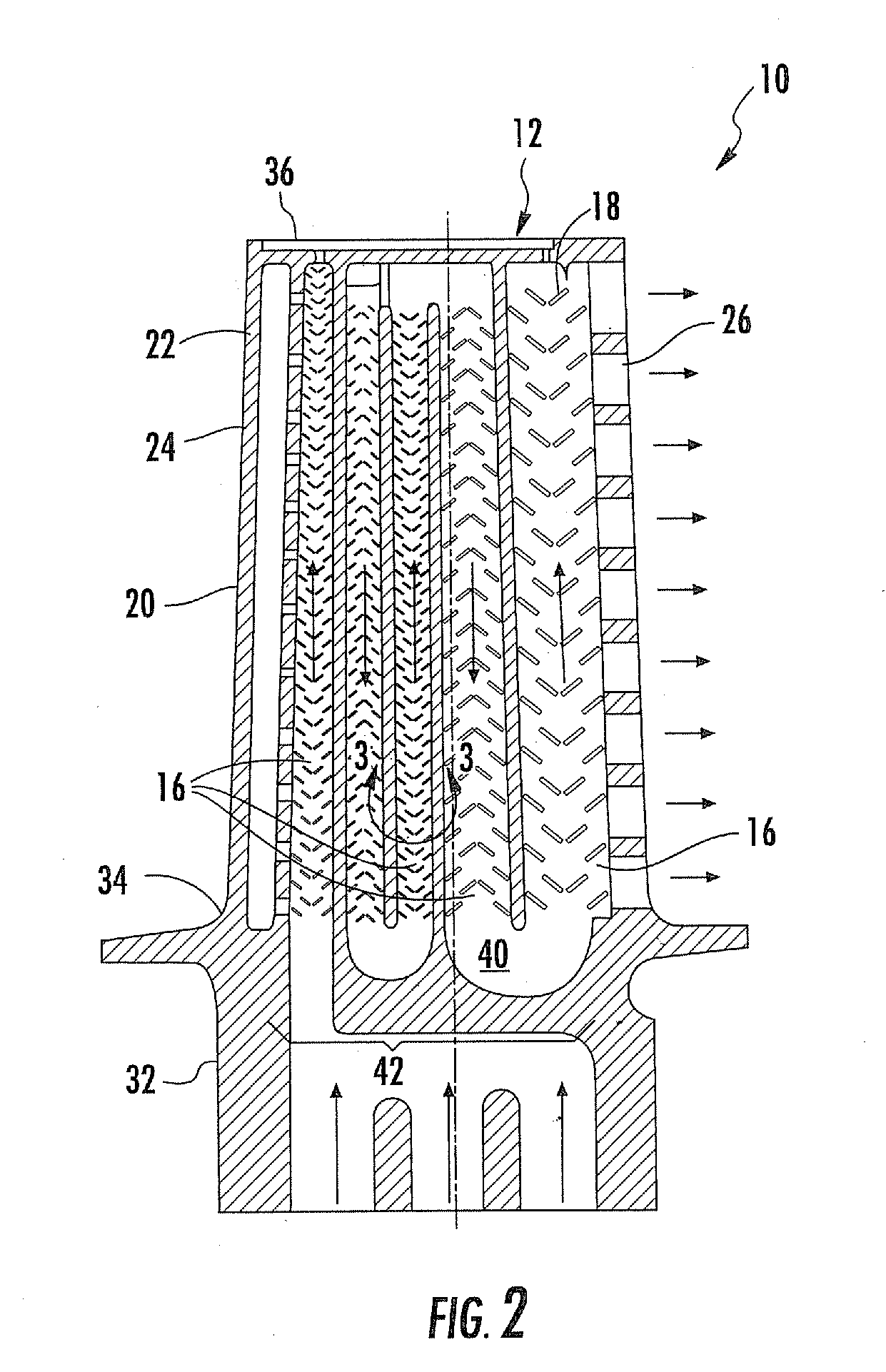
[0015]As shown in FIGS. 1-5, this invention is directed to a turbine airfoil cooling system 10 configured to cool internal and external aspects of a turbine airfoil 12 usable in a turbine engine. In at least one embodiment, the turbine airfoil cooling system 10 may be configured to be included within a turbine blade, as shown in FIGS. 1-5. While the description below focuses on a cooling system 10 in a turbine blade 12, the cooling system 10 may also be adapted to be used in a stationary turbine vane. The turbine airfoil cooling system 10 may be formed from a cooling system 10 having one or more cooling channels 16 having any appropriate configuration, as shown in FIGS. 2-5. The cooling channels 16 may include a plurality of turbulators 18 for creating vortices within the cooling channels 16 to increase the internal convective cooling potential of the cooling system, thereby increasing the overall performance of the cooling system 10.

[0016]The turbine airfoil 12 has a generally elon...


PUM


Abstract

A turbine airfoil usable in a turbine engine and having at least one cooling system is disclosed. At least a portion of the cooling system may include one or more cooling channels having a plurality of turbulators protruding from an inner surface and positioned generally nonorthogonal and nonparallel to a longitudinal axis of the airfoil cooling channel. The configuration of turbulators may create a higher internal convective cooling potential for the blade cooling passage, thereby generating a high rate of internal convective heat transfer and attendant improvement in overall cooling performance. This translates into a reduction in cooling fluid demand and better turbine performance.

Description

FIELD OF THE INVENTION[0001]This invention is directed generally to turbine airfoils, and more particularly to hollow turbine airfoils having cooling channels for passing fluids, such as air, to cool the airfoils.BACKGROUND[0002]Typically, gas turbine engines include a compressor for compressing air, a combustor for mixing the compressed air with fuel and igniting the mixture, and a turbine blade assembly for producing power. Combustors often operate at high temperatures that may exceed 2,500 degrees Fahrenheit. Typical turbine combustor configurations expose turbine vane and blade assemblies to these high temperatures. As a result, turbine vanes and blades must be made of materials capable of withstanding such high temperatures. In addition, turbine vanes and blades often contain cooling systems for prolonging the life of the vanes and blades and reducing the likelihood of failure as a result of excessive temperatures.[0003]Typically, turbine blades are formed from an elongated por...

Claims


Application Information

Patent Timeline
Patent Type & Authority Applications(United States)
IPC IPC(8): F01D5/18
CPCF01D5/182F01D5/187F01D5/186
Inventor LEE, CHING-PANG
Owner SIEMENS ENERGY INC
Why Eureka
Try Eureka