Turbine airfoil with an internal cooling system having trip strips with reduced pressure drop

a technology of internal cooling system and trip strip, which is applied in the field of hollow turbine airfoils, can solve the problems of increasing the cooling capacity of the cooling system but having inherent limitations, and the likelihood of failure, and achieves the effects of higher internal convective cooling potential, higher velocity, and higher heat transfer

Inactive Publication Date: 2017-01-24
SIEMENS AG
View PDF27 Cites 1 Cited by
  • Summary
  • Abstract
  • Description
  • Claims
  • Application Information

AI Technical Summary

Benefits of technology

[0008]During use, cooling fluid is passed into the cooling system, including the cooling channel At least a portion of the cooling fluid contacts the trip strip In particular, at least a portion of the cooling fluid contacts the first section of the upstream surface, where the cooling fluid is directed upwardly at an angle that is nonparallel and nonorthogonal to the inner surface forming the cooling channel. The cooling fluid then strikes the second section of the upstream surface, which causes the cooling fluid to be directed at an even steeper angle away from the inner surface. The cooling fluid then flows past the second section and along the top surface. While passing the first section, the second section and the top surface, heat is being passed from the trip strip to the cooling fluid via convection The cooling fluid flows past the top surface and then a portion of the cooling fluids forms a circular flow of cooling fluids that flow against the concave downstream surface The formation of eddies on the downstream surface is mitigated by accommodating the primary vortex or eddie and ensuring higher velocity and thus higher heat transfer on the downstream surface as compared to the low velocity recirculation in conventional square or rectangle cross section trip strips. This uniquely shaped trip strip cross-sectional area creates higher internal convective cooling potential for the turbine blade cooling channel, thus generating a high rate of internal convective heat transfer and efficient overall cooling system performance. This performance equates to a reduction in cooling demand and better turbine engine performance. An advantage of the turbine airfoil cooling system is that the system is configured to cool cooling channels and because of its configuration is particularly well suited to cool cooling channels in industrial gas turbine engines.
[0009]Another advantage of the cooling system is that the configuration of the cross-sectional area of the trip strip reduces the amount of pressure drop typically associated with trip strips

Problems solved by technology

In addition, turbine vanes and blades often contain cooling systems for prolonging the life of the vanes and blades and reducing the likelihood of failure as a result of excessive temperatures
Such configurations increase the cooling capacity of a cooling system but have inherent limitations, as shown by the loss regions 5 shown in FIG. 1.

Method used


Image

  • Turbine airfoil with an internal cooling system having trip strips with reduced pressure drop
  • Turbine airfoil with an internal cooling system having trip strips with reduced pressure drop
  • Turbine airfoil with an internal cooling system having trip strips with reduced pressure drop

Examples


Embodiment Construction

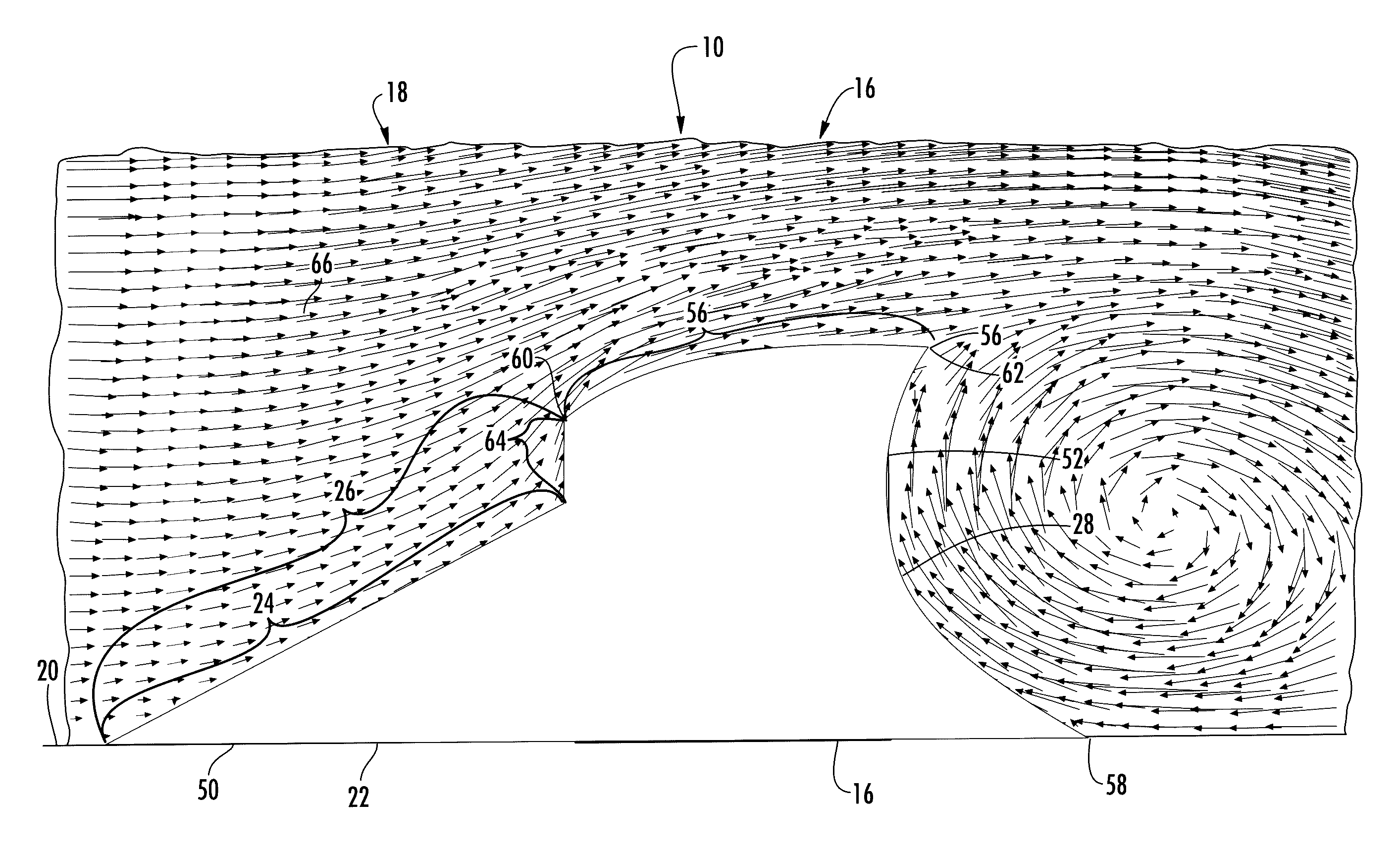
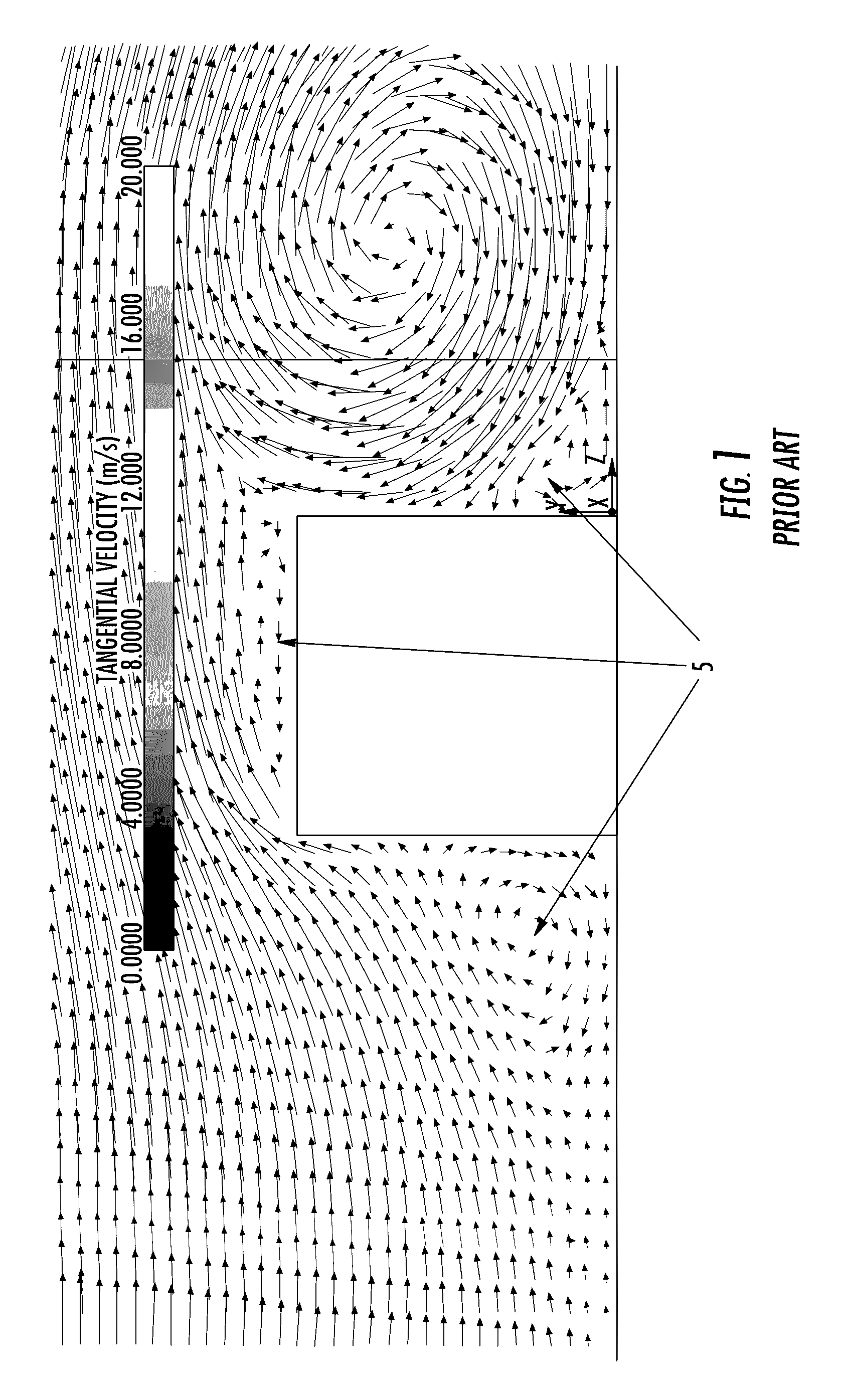
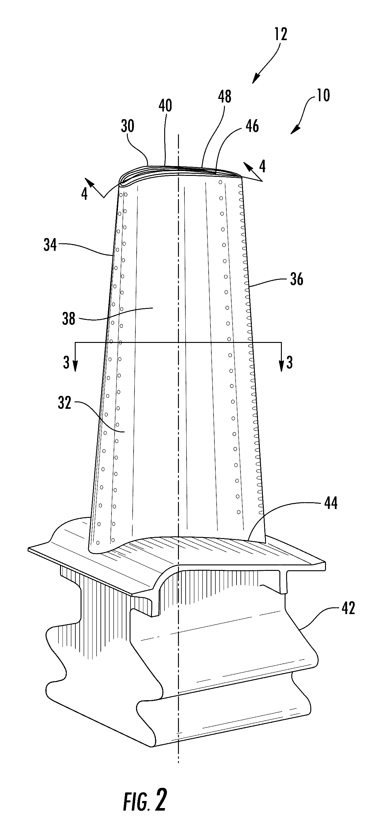
[0016]As shown in FIGS. 2-5, a turbine airfoil 10 usable in a turbine engine 12 and having at least one cooling system 14 with an efficient trip strip 16 is disclosed. At least a portion of the cooling system 14 may include one or more cooling channels 18 having one or more trip strips 16 protruding from an inner surface 20 forming the cooling channel 18, as shown in FIGS. 3 and 4. The trip strip 16 may have improved operating characteristics including enhanced heat transfer capabilities and a substantial reduction in pressure drop typically associated with conventional trip strips. In at least one embodiment, as shown in FIG. 5, the trip strip 16 may have a cross-sectional area 22 with a first section 24 of an upstream surface 26 of the trip strip 16 being positioned nonparallel and nonorthogonal to a surface 20 forming the cooling system channel 18 extending upstream from the trip strip 16 and a concave shaped downstream surface 28 of the trip strip 16 that enables separated flow ...


PUM


Abstract

A turbine airfoil usable in a turbine engine and having at least one cooling system with an efficient trip strip is disclosed At least a portion of the cooling system may include one or more cooling channels having one or more trip strips protruding from an inner surface forming the cooling channel. The trip strip may have improved operating characteristics including enhanced heat transfer capabilities and a substantial reduction in pressure drop typically associated with conventional trip strips In at least one embodiment, the trip strip may have a cross-sectional area with a first section of an upstream surface of the trip strip being positioned nonparallel and nonorthogonal to a surface forming the cooling system channel extending upstream from the at least one trip strip and a concave shaped downstream surface of the at least one trip strip that enables separated flow to reattach to the cooling fluid flow.

Description

FIELD OF THE INVENTION[0001]This invention is directed generally to turbine airfoils, and more particularly to hollow turbine airfoils having cooling channels for passing fluids, such as air, to cool the airfoilsBACKGROUND[0002]Typically, gas turbine engines include a compressor for compressing air, a combustor for mixing the compressed air with fuel and igniting the mixture, and a turbine blade assembly for producing power. Combustors often operate at high temperatures that may exceed 2,500 degrees Fahrenheit Typical turbine combustor configurations expose turbine vane and blade assemblies to these high temperatures. As a result, turbine vanes and blades must be made of materials capable of withstanding such high temperatures. In addition, turbine vanes and blades often contain cooling systems for prolonging the life of the vanes and blades and reducing the likelihood of failure as a result of excessive temperatures[0003]Typically, turbine blades are formed from an elongated portio...

Claims


Application Information

Patent Timeline
Patent Type & Authority Patents(United States)
IPC IPC(8): F01D5/18F01D9/02
CPCF01D5/188F01D5/187F01D9/02F05D2240/127F05D2250/711F05D2250/712F05D2260/2212F05D2260/22141
Inventor RODRIGUEZ, JOSE L.GOLSEN, MATTHEW J.
Owner SIEMENS AG
Why Eureka
Try Eureka