Shim member, die coater, and method for producing coating film

Inactive Publication Date: 2013-09-12
NITTO DENKO CORP
View PDF27 Cites 12 Cited by
  • Summary
  • Abstract
  • Description
  • Claims
  • Application Information

AI Technical Summary

Benefits of technology

[0030]As described above, according to the present invention

Problems solved by technology

For this reason, an operation for changing

Method used


Image

  • Shim member, die coater, and method for producing coating film
  • Shim member, die coater, and method for producing coating film
  • Shim member, die coater, and method for producing coating film

Examples


reference example 1

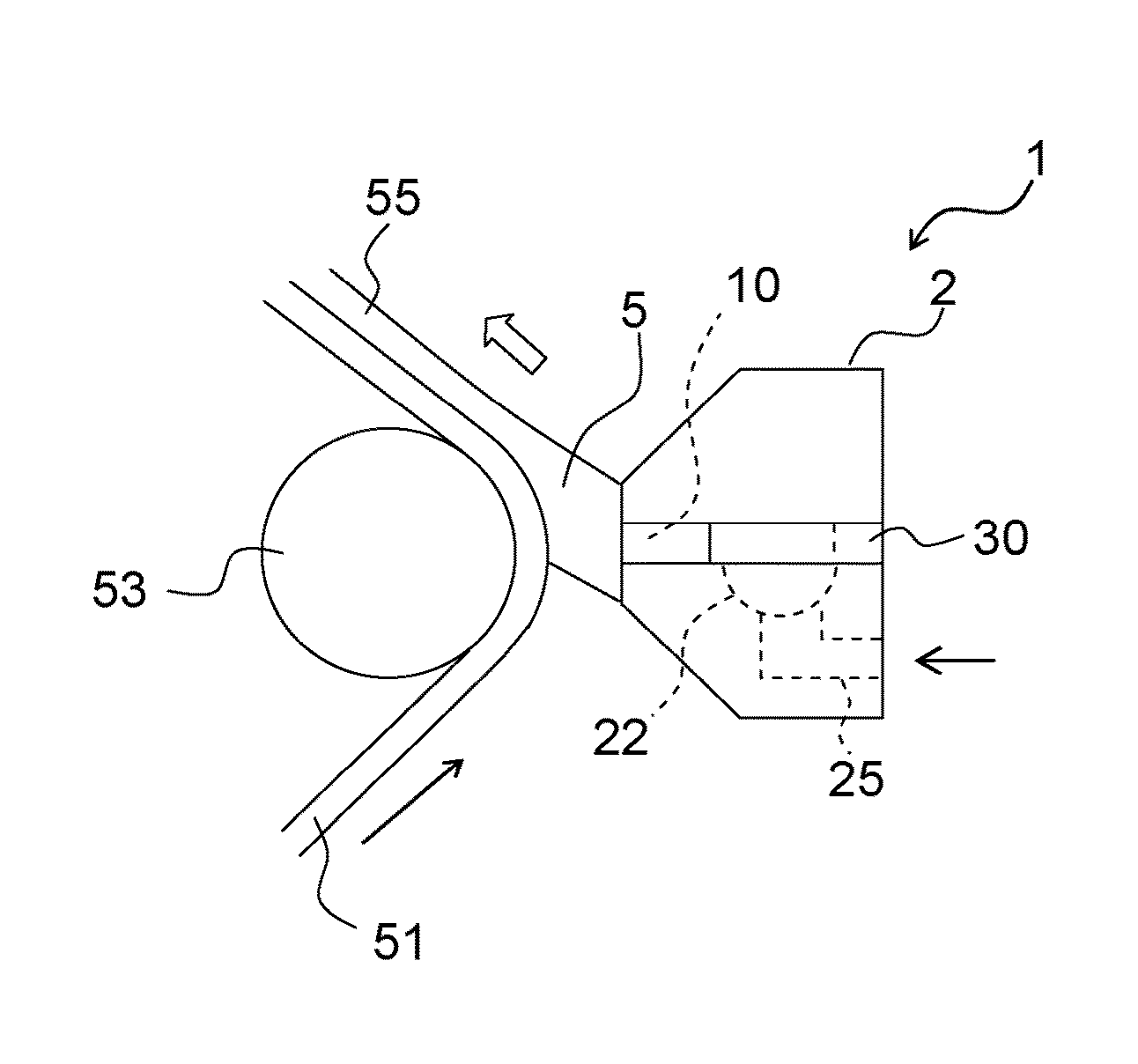
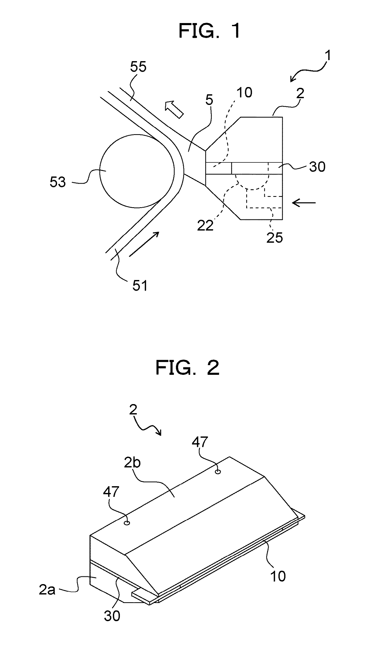
[0166]As is illustrated in FIG. 4C, a die coater 1 was used which was provided with a shim member having a nose portion 34 with a rectangular shape and was illustrated in FIG. 1.

[0167]A liquid in which an acrylic tackiness agent was dissolved in a mixture of toluene and ethyl acetate was used as the coating liquid. A polyethylene terephthalate (PET) film (MRF38, 38 μm in thickness and 1,300 mm in width, made by Mitsubishi Plastics, Inc.) was used as a substrate.

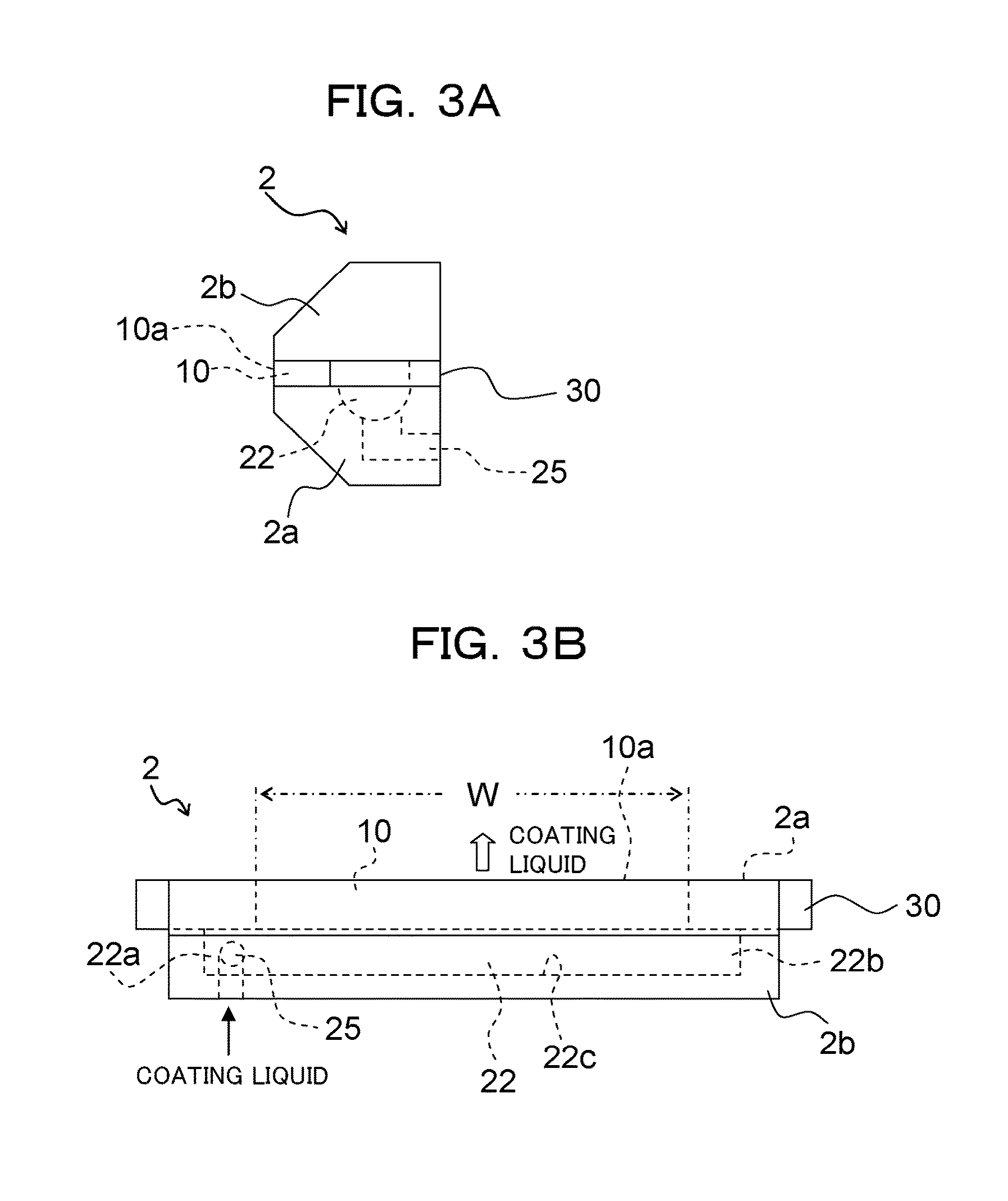
[0168]The transportation speed of the substrate in the longitudinal direction was set at 28 m / min, and the coating width W thereof was set at 1,280 mm. The coating liquid was applied onto the substrate with the use of the above described die coater 1, and then was dried. Thereby, a coating film was formed on the substrate. The thickness of the formed coating film was measured throughout the width direction with the use of an optical interference type of thickness indicator (MCPD series, made by Otsuka Electronics Co., Ltd.). ...

reference example 2

[0169]As illustrated in FIG. 6C and FIG. 19, a nose portion 34 was used which was formed so that an opening 10a side in the inside of the nose portion 34 (the upper side in each figure) was chamfered, in other words, so that the distance from each other expanded toward the opening 10a side. In addition, as illustrated in FIG. 19, an inclining angle θ of the chamfered portion with respect to the end edge 34a (the vertical direction in FIG. 19) of the inside of the nose portion 34 was set at 30°, a length of the chamfered portion from the end edge 34a of the inside in the width direction of the nose portion 34 (the amount of chamfer, in other words, an amount of an expanded distance in the end edge in the opening 10a side of the one nose portion 34, between the end edge and an end edge in the opening 10a side of the other nose portion 34) L was set at 5 mm, and the coating width (a distance between the end edges in the opening 10a side in the nose portions 34) W was set at 1,280 mm.

[0...

reference example 3

[0171]The coating liquid was applied onto the substrate, and the thickness of the coating film which was formed on the substrate was measured throughout the width direction in a similar way to that in Reference Example 2, except that the length L (the amount of the chamfer) of the chamfered portion from the end edge 34a of the inside in the width direction was set at 10 mm. The obtained result is illustrated in FIG. 20.

[0172]As is illustrated in FIG. 20, in the case where the chamfered portion is provided (5 mm and 10 mm), humps or rounded protrusions in both ends in the width direction of the coating film can be more suppressed than those in the case where the chamfered portion is not provided (0 mm). Thereby, it was found that the shim member could more surely uniformize the thickness of the coating film throughout the width direction.

[0173]In addition, in the present reference example, in the case where the amount of the chamfer was 10 mm, the above described humps or rounded pro...


PUM


Abstract

Provided is a shim member which is sandwiched between two die blocks provided in a the coater, and has the U shape formed by a base end portion which is arranged so as to extend in a longitudinal direction of the slot, and a pair of extending portions which extend toward a nose portion of the die from both ends in a longitudinal direction of the base end portion, wherein a first portion which is a nose portion of at least one extending portion or the whole of at least the one extending portion, out of the pair of the extending portions, and a second portion which is the remaining portion including at least the base end portion, are structured so as to be separable from each other.

Description

CROSS REFERENCE TO RELATED APPLICATION[0001]The present application claims priority of Japanese Patent Application Nos. 2012-050944 and 2012-266744, which are incorporated in the specification of the present application by reference.BACKGROUND OF THE INVENTION[0002]1. Field of the Invention[0003]The present invention relates to a shim member, a die coater, and a method for producing a coating film.[0004]2. Description of the Related Art[0005]Conventionally, a die coater which has a slot that discharges a coating liquid therefrom provided in a die is known as one of coating applicators. The die coater extrudes the supplied coating liquid from the slot, and also applies the coating liquid onto a substrate such as a film, by bringing the substrate close to the slot and moving the substrate relatively with respect to the slot.[0006]There is the case in which this type of die coater applies the coating liquid to the substrate so as to form variously different coating widths according to ...

Claims


Application Information

Patent Timeline
IPC IPC(8): B05C21/00B05D1/26
CPCB05C21/00B05C5/0266B05D1/265B05C5/02B05D1/26
Inventor KOMATSUBARA, MAKOTOMICHIHIRA, HAJIME
Owner NITTO DENKO CORP
Why Eureka
Try Eureka