Decoupler assembly having limited overrunning capability

a technology of decoupler assembly and overrunning capability, which is applied in the direction of couplings, slip couplings, gearings, etc., can solve the problems of high manufacturing cost, inability to apply coatings to the interior surface of wrap springs, and inability to engage wrap springs. the coating process is made more difficult and expensive than it would otherwis

Active Publication Date: 2013-09-12
LITENS AUTOMOTIVE INC
View PDF13 Cites 60 Cited by
  • Summary
  • Abstract
  • Description
  • Claims
  • Application Information

AI Technical Summary

Benefits of technology

[0008]The decoupler assembly may be used as part of a BAS (Belt-Alternator-Start) system for a vehicle. In an embodiment, the vehicle includes an engine that has crankshaft, a crankshaft pulley, and a belt that is engaged with the crankshaft pulley and with an alternator. The BAS system includes a decoupler assembly mountable to the shaft of the alternator. The decoupler assembly includes a hub that is adapted to be coupled to the shaft such that the shaft co-rotates with the hub about a rotational axis, a pulley rotatably coupled to the hub, and having an outer periphery that is adapted to engage the endless drive member, a helical torsion spring concentric with the rotational axis and having a first axial face and a second axial face, and having a plurality of coils which are spaced apart by a plurality of gaps, a first engagement structure positioned between the torsion spring and one of the hub and the pulley, and a second engagement structure p

Problems solved by technology

However, it can be costly to manufacture for various reasons.
Thus, coatings, which typically have a relatively high variability in their thickness, cannot typically be applied to its interior surface that engages the wrap spring.
Thus the coating process is made more difficult and expensive than it would otherwise

Method used


Image

  • Decoupler assembly having limited overrunning capability
  • Decoupler assembly having limited overrunning capability
  • Decoupler assembly having limited overrunning capability

Examples


Embodiment Construction

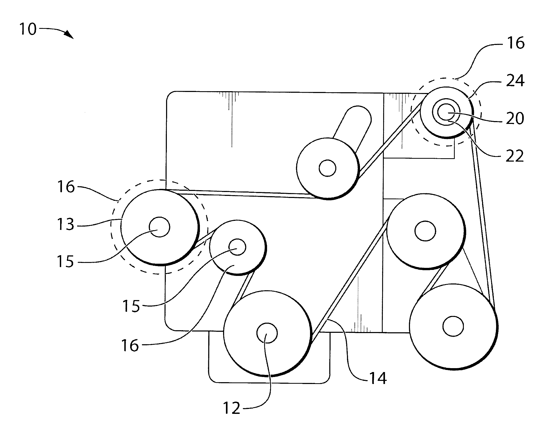
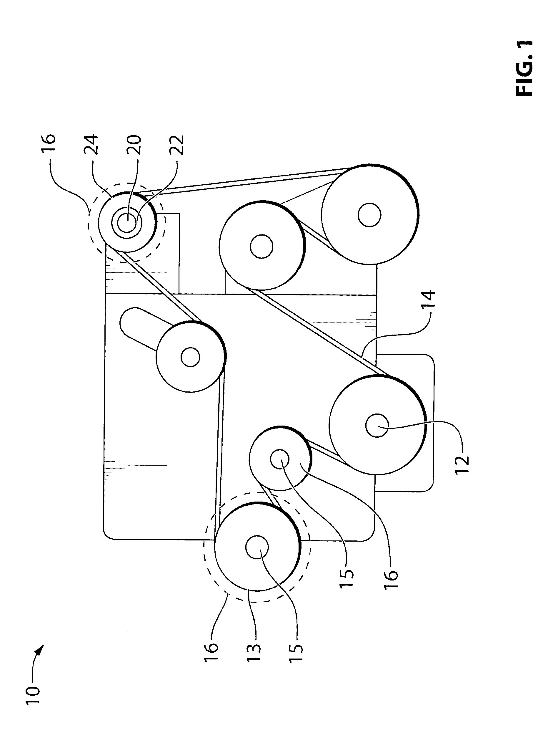
[0030]Reference is made to FIG. 1, which shows an engine 10 for a vehicle. The engine 10 includes a crankshaft 12 which drives an endless drive element, which may be, for example, a belt 14. Via the belt 14, the engine 10 drives a plurality of accessories 16 (shown in dashed outlines), such as an alternator and a compressor. Each accessory 16 includes an input drive shaft 15 with a pulley 13 thereon, which is driven by the belt 14. A decoupler assembly 20 is provided instead of a pulley, between the belt 14 and the input shaft 15 of any one or more of the belt driven accessories 16. The decoupler assembly 20 transfers torque between the belt 14 and the shaft 15 but automatically decouples the shaft 15 from the belt 14 when the belt 14 decelerates relative to the shaft 15. Additionally, the decoupler assembly 20 allows the speed of the belt 14 to oscillate relative to the shaft 15. Thus, oscillations in the belt speed that are the result of oscillations in the speed of the crankshaft...


PUM


Abstract

In one aspect, a decoupler assembly is provided for use between a shaft and an endless drive member that is used to drive the shaft. The decoupler assembly includes a pulley, a hub and an isolator spring that is preferably a coiled torsion spring. The two ends of the spring are engageable, at least indirectly, with the pulley and the hub for the transfer of torque therebetween. At least one of the ends of the spring engages an engagement structure (on either the pulley or the hub) that includes a helical axial shoulder and a driver wall. The spring transfers torque in one direction through the driver wall (e.g. when the pulley overruns the hub), but the spring end is not fixedly connected to the driver wall. When the hub overruns the pulley, there is relative rotation between the spring and whichever of the hub and pulley it is not fixedly connected to. Accordingly, there is relative rotation between the spring end and the helical axial shoulder and the driver wall. This causes the spring end to separate from the driver wall and ride up the helical axial shoulder. This causes the spring to compress axially. The spring coils have a selected amount of spacing so that the spring can be compressed by a selected amount axially. This sets the amount of relative rotation (and the amount of overrun) that is available between the pulley and the hub in the situation when the hub overruns the pulley.

Description

FIELD OF THE INVENTION[0001]The present invention relates to decoupler assemblies and more particularly to decoupler assemblies for alternators.BACKGROUND OF THE INVENTION[0002]It is known to provide a decoupling mechanism on an accessory, such as an alternator, that is driven by a belt from an engine in a vehicle. Such a decoupling mechanism, which may be referred to as a decoupler, permits the associated accessory to operate temporarily at a speed that is different than the speed of the belt. For example, when there is a sudden stoppage of the belt when the belt was running and driving rotation of the alternator shaft, the decoupler permits the alternator shaft to continue rotating temporarily as a result of inertia until it decelerates to a stop as a result of drag, thereby reducing the stress on the alternator shaft. As another example, the decoupler permits the alternator shaft to rotate at a relatively constant speed even though the crankshaft from the engine undergoes a cycle...

Claims


Application Information

Patent Timeline
IPC IPC(8): F16H61/00
CPCB60K25/02B60K2025/022F02B67/06F16D3/10F16D7/00F16D41/206F16H55/36F16H2055/363F16D3/12F16F15/1216B60K25/00F16H7/20F16H2055/366B60K26/02
Inventor MARION, PATRICK
Owner LITENS AUTOMOTIVE INC
Why Eureka
Try Eureka