Built-in antenna for electronic device

Active Publication Date: 2013-09-19
SAMSUNG ELECTRONICS CO LTD
View PDF3 Cites 37 Cited by
  • Summary
  • Abstract
  • Description
  • Claims
  • Application Information

AI Technical Summary

Benefits of technology

[0014]Preferably, during operation of the first antenna radiator, the second antenna radiator is disconnected from the RF end but is electromagnetically coupled to the first antenna radiator in a manner which improves the antenna performance of the first antenna radiator. The

Problems solved by technology

However, with ground pad switching technology, it is difficult to cover a penta band that includes the relatively high bands of LTE Band7 and LTE Band11.
However, using this scheme, the amount of frequency shift obtainable is limited to about 60 MHz.
This limitation stems from the difficulty in securing as much spaced distance between radiators. as desired.
Ground pad s

Method used


Image

  • Built-in antenna for electronic device
  • Built-in antenna for electronic device
  • Built-in antenna for electronic device

Examples


Embodiment Construction

[0021]Exemplary embodiments of the present invention will be described herein below with reference to the accompanying drawings. In the following description, well-known functions or constructions are not described in detail since they would obscure the invention in unnecessary detail. And, terms described below, which are defined considering functions in the present invention, can differ in meaning depending on user and operator's intent or practice. Therefore, the terms should be understood on the basis of the disclosure throughout this specification.

[0022]The following detailed description illustrates and describes a portable terminal as an electronic device, but this does not intend to limit the scope and spirit of the invention. For example, the present invention shall be applicable to electronic devices of various fields used for communication, although not portable.

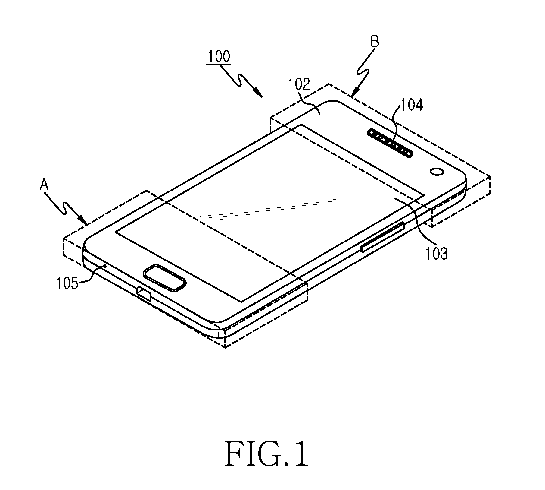
[0023]FIG. 1 is a perspective view illustrating a portable terminal as an electronic device installing a built-i...


PUM


Abstract

A built-in antenna for an electronic device is provided. The built-in antenna includes a substrate, a 1st antenna radiator with at least two radiating portions, a 2nd antenna radiator, and a switching means. The substrate has a conductive area and a non-conductive area. The 2nd antenna radiator is arranged within the non-conductive area of the substrate and fed by a Radio Frequency (RF) end of the substrate. The 2nd antenna radiator is configured to operate at a band different from at least one operating band of the 1st antenna radiator, and is fed by the RF end in a position adjacent the 1st antenna radiator. The switching means switches to selectively feed the 1st antenna radiator and the 2nd antenna radiator.

Description

CLAIM OF PRIORITY[0001]This application claims priority under 35 U.S.C. §119(a) to a Korean Patent Application filed in the Korean Intellectual Property Office on Mar. 19, 2012 and assigned Serial No. 10-2012-0027681, the contents of which are herein incorporated by reference.BACKGROUND OF THE INVENTION[0002]1. Technical Field[0003]The present disclosure relates generally to a built-in antenna for an electronic device, and more particularly, to a multi-band built-in antenna electronic device.[0004]2. Description of the Related Art[0005]A portable terminal is generally considered any hand-held electronic device that can transmit and / or receive an RF signal. Examples of portable terminals include cell phones, smart phones, tablet PCs, personal digital assistants (PDAs), game devices, e-books, digital cameras and navigation devices. As technology has advanced and more functionality has been added to mainstream models, the goal of providing a slim and aesthetic design has remained an im...

Claims


Application Information

Patent Timeline
IPC IPC(8): H01Q1/50H01Q5/364H01Q5/371H01Q5/378
CPCH01Q1/50H01Q1/243H01Q9/42H01Q5/378H01Q5/364H01Q5/371H01Q21/30H01Q1/24H01Q1/46H01Q5/00
Inventor LEE, KYUNG-JONGKIM, SEUNG-HWANKIM, DONG-HWANKIM, AUSTINLEE, YOUNG-SUNGLEE, JAE-HOCHUN, JAE-BONG
Owner SAMSUNG ELECTRONICS CO LTD
Why Eureka
Try Eureka