Method and System for Removal of Noise in Signal

a noise extraction and signal technology, applied in the field of noise extraction from signals, can solve the problems of contaminated uwb signals through the channel, large frequency allocation and utilization problems, signal noise, etc., and achieve the effect of reducing target amplitudes

Active Publication Date: 2013-09-19
UNITED STATES OF AMERICA AS REPRESENTED THE SEC OF THE ARMY THE
View PDF17 Cites 64 Cited by
  • Summary
  • Abstract
  • Description
  • Claims
  • Application Information

AI Technical Summary

Benefits of technology

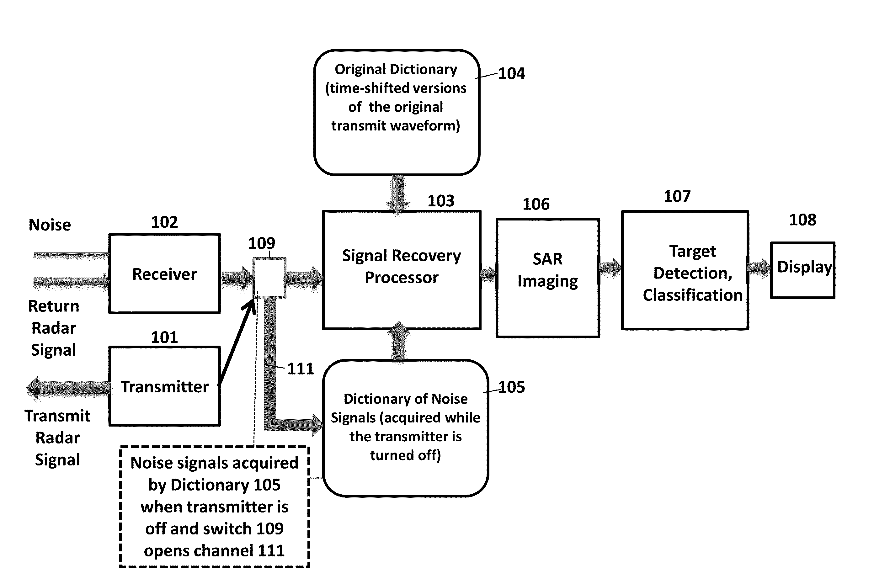
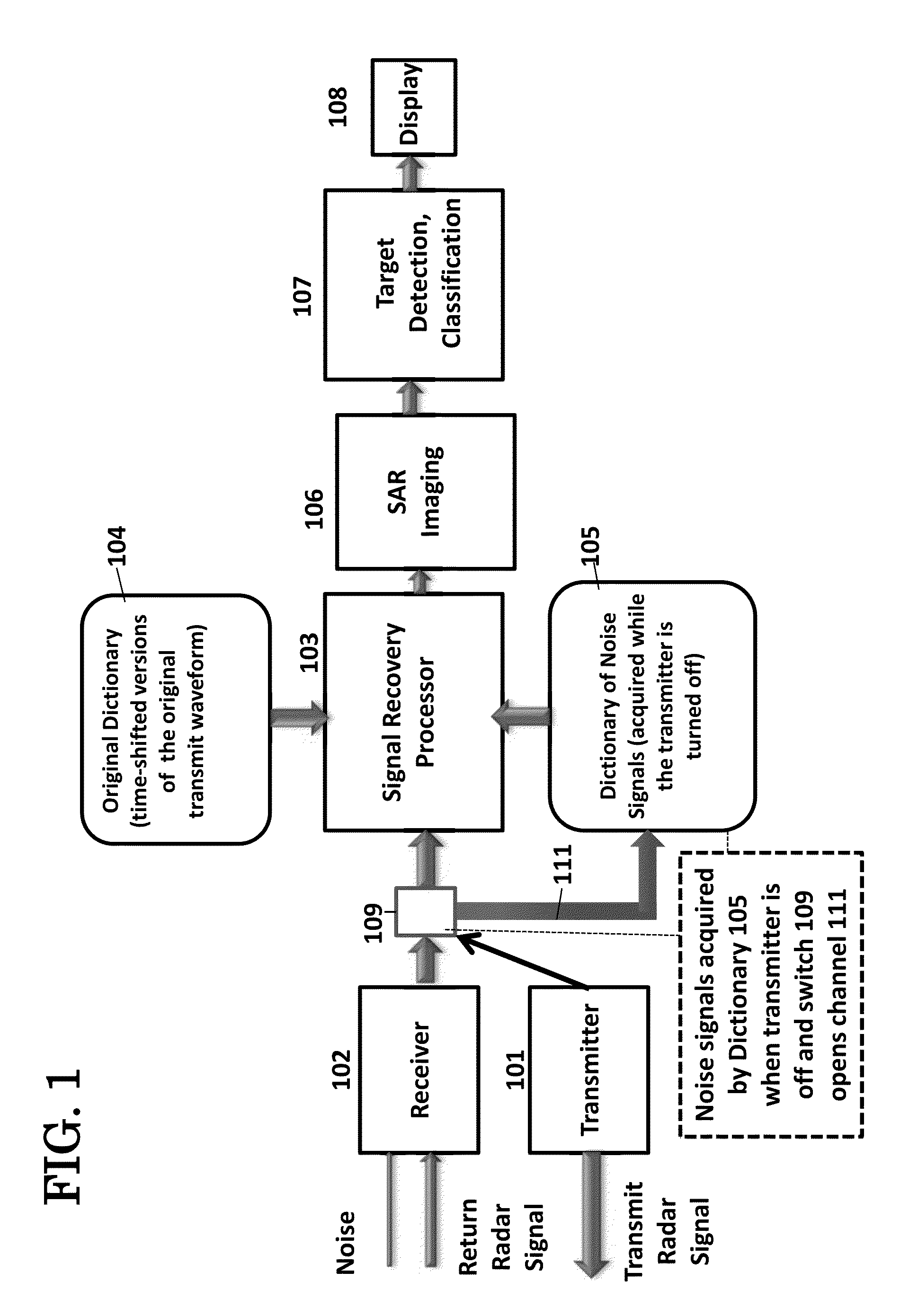
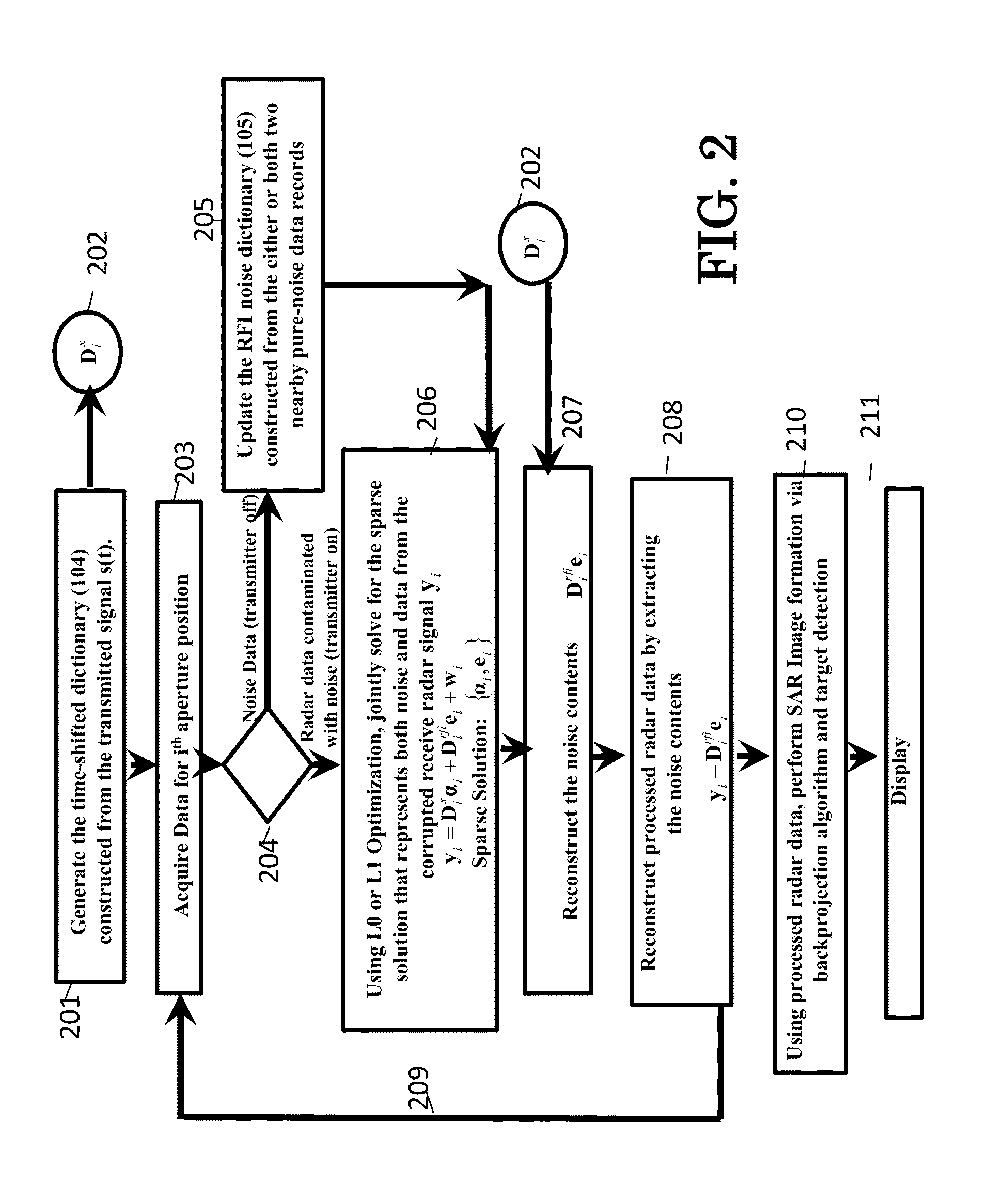
[0009]A preferred embodiment of the present invention is directed to a technique that directly estimates the interference noise components in the time domain and extracts them from radar data. An advantage of this technique is that the time-domain extraction of RFI noise does not result in (i) large sidelobes in the time domain of the received signal and (ii) reduced target amplitudes. The second advantage is that it is completely adaptive with the changing environment and does not assume any knowledge (amplitude, frequency band, modulation scheme, etc.) of the sources of interference. The invented technique simultaneously estimates (i) the signal embedded in interference noise (which may be, for example, a radar signal) with large amplitudes and (ii) the interference noise signal.

Problems solved by technology

The frequency allocation and utilization problem becomes a big challenge and only gets worse over time since additional radar and communication systems that need the penetration feature must operate in this low-frequency region of the spectrum.
There are at least two challenges for any UWB system (radar or communications).
The received UWB signal through the channel is contaminated by signals from all systems that operate in the same spectrum.
In the time domain, the signal is very noisy and might he embedded in the noise floor.
Except for targets with very large amplitudes, most targets may not be detectable in the presence of interference noise.
This technique results in severe sidelobes in the time or spatial domain of the output data and imagery due to the sharp transitions (frequency samples with no information) in the frequency domain.
interference signals from competing frequencies are essentially large amplitude noise that often masks the underlying radar signals.
Depending on the nature of the interference noise sources, this notch-filter approach would result in (i) large sidelobes in the time domain of the received signal and (ii) reduced target amplitudes.
However, the technique requires complete knowledge of the interference sources.
This assumption is no longer valid with the current frequency spectrum, in which most of the communications and TV channels are broadcasting using various digital modulation schemes.
Thus, it is not possible to use the Miller technique to estimate these RF interference (RFI) components with digital modulation contents.
Another challenge for any UWB system (radar or communications) is that the system must avoid transmitting energy in certain frequency bands that are specified by the frequency management agencies.
The notches in the frequency domain translate to severe noise and artifacts in the resulting data and imagery.
Since the results from multiple bands are interpreted independently, this creates another challenge for the detection and discrimination stages.

Method used


Image

  • Method and System for Removal of Noise in Signal
  • Method and System for Removal of Noise in Signal
  • Method and System for Removal of Noise in Signal

Examples


Embodiment Construction

[0041]The embodiments herein and the various features and advantageous details thereof are explained more fully with reference to the non-limiting embodiments that are illustrated in the accompanying drawings and detailed in the following description. Descriptions of well-known components and processing techniques are omitted so as to not unnecessarily obscure the embodiments herein. The examples used herein are intended merely to facilitate an understanding of ways in which the embodiments herein may be practiced and to further enable those of skill in the art to practice the embodiments herein. Accordingly, the examples should not be construed as limiting the scope of the embodiments herein.

[0042]The terminology used herein is for the purpose of describing particular embodiments only and is not intended to limit the fall scope of the invention. As used herein, the singular forms “a”, “an” and “the” intended to include the plural thrills as well, unless the context clearly indicate...


PUM


Abstract

A method and system for reception of electromagnetic waves in which interference with radio frequencies of other electronics devices occurs comprising;
  • at least one transmitter for transmitting electromagnetic radiation at a wide range of frequencies;
  • at least one receiver fix receiving the received signal comprising the first electromagnetic radiation and RF interfering signal data;
  • a first memory portion for storing transmitted signal waveforms;
  • a second memory portion for storing RF interfering signal data;
  • a switch for periodically allowing the RF interfering signal data to enter the second memory portion from the receiver;
  • the at least one processor operating to process and compare the received, signal containing RE signal data and first electromagnetic radiation by matching the received signal against data relating to the transmitted signal waveforms from the first memory portion and RF interfering signal data from the second memory portion, and extract the RF interfering signal data.

Description

CROSS REFERENCE TO RELATED APPLICATIONS[0001]This application is a continuation-in-part of and claims priority to U.S. patent application Ser. No. 13 / 477,282 entitled “Method and System for Recovery of Missing Spectral Information in Wideband Signal” by Lam H. Nguyen and Thong Do filed May 22, 2012 (ARL 11-77CIP), which is a continuation-in-part and claims priority to U.S. patent application Ser. No. 13 / 416,062 entitled “Apparatus and Method for Sampling and Reconstruction of Wide Bandwidth Signals below Nyquist Rate,” by Lam H. Nguyen and Trac Tran filed Mar. 9, 2012; both of which are hereby incorporated by reference.STATEMENT OF GOVERNMENT INTEREST[0002]The embodiments herein may be manufactured, used, and / or licensed by or for the United States Government without the payment of royalties thereon.BACKGROUND OF THE INVENTION[0003]The present invention relates to, inter alia, noise extraction from a signal. The signal may be used, for example, in the generation of images from proje...

Claims


Application Information

Patent Timeline
Patent Type & Authority Applications(United States)
IPC IPC(8): H04B15/00
CPCG01S13/0209G01S13/90H04B15/00H04B17/345H04B1/71632H04L27/0004G01S7/023
Inventor NGUYEN, LAM HUYTRAN, TRAC D.
Owner UNITED STATES OF AMERICA AS REPRESENTED THE SEC OF THE ARMY THE
Why Eureka
Try Eureka