
Soil Moisture Sensor

a technology of soil moisture and sensor, which is applied in the direction of automatic control, process and machine control, instruments, etc., can solve the problems of ineffective means of conserving resources, over-watering and under-watering landscaping, and long installation time. , to achieve the effect of ensuring the installation, the installation method is difficult, and the installation time is long

Active Publication Date: 2013-10-03
TORO CO THE
View PDF5 Cites 22 Cited by
  • Summary
  • Abstract
  • Description
  • Claims
  • Application Information

AI Technical Summary

Benefits of technology

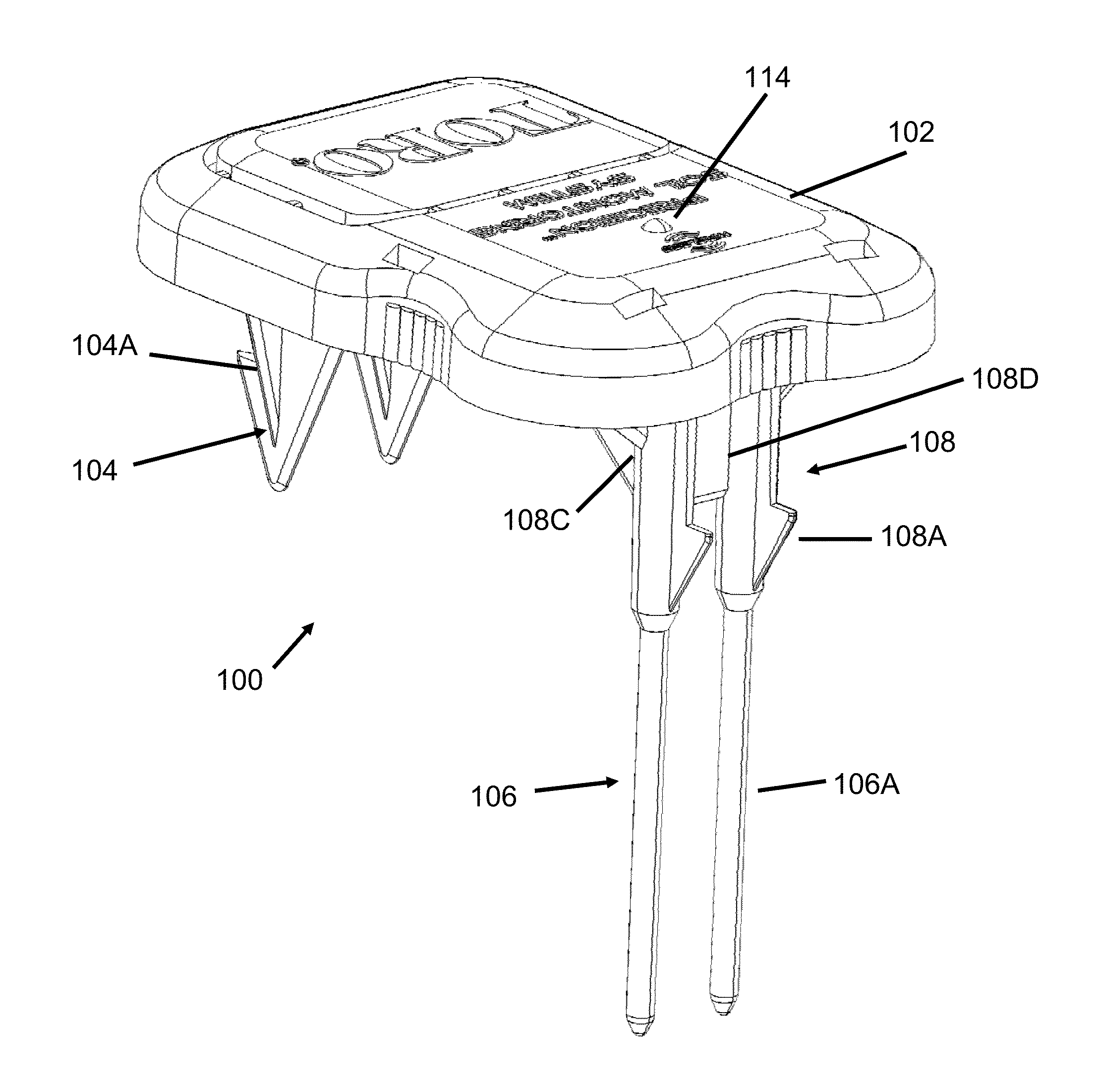
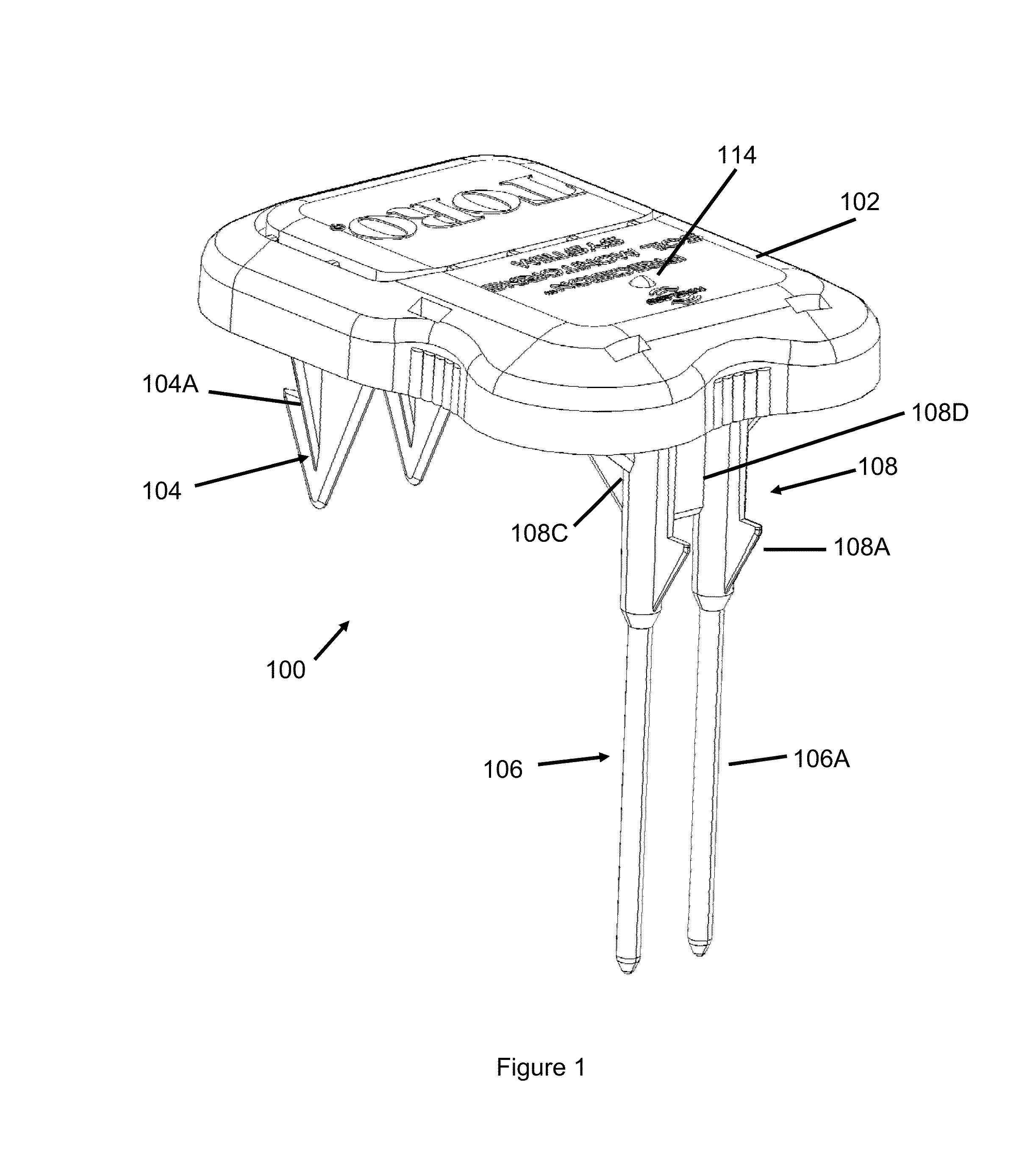
The present invention provides a soil moisture sensor that can interrupt an irrigation schedule of an irrigation controller. It consists of a flat body with two lower electrodes and two lower anchoring barbs. The sensor receives moisture readings and compares it to a predetermined moisture interrupt value or limit, over which irrigation is interrupted. The technical effect of the invention is to provide an efficient and effective solution for controlling irrigation based on soil moisture levels, leading to improved crop health and reduced water consumption.

Problems solved by technology

In most situations this proves to be an ineffective means of conserving resources due to the inconsistent and inefficient methods followed by the operator.
In fact, quite often the operator ignores the need to suspend the watering cycle altogether, and in some cases neglects to resume the watering cycle when required, leading to both over-watered and under-watered landscaping.
It is because of this unreliable and inconvenient manual method that environmental sensors were developed that allow for an automatic interruption of the controller due to an environmental condition.
One of the major drawbacks of the conventional environmental sensors is the extensive installation time and difficult methods required for a proper installation.
If the soil is not restored properly, water and fertilizer can drain down along the hole to the sensor and corrupt the sensor readings.
Digging a hole and refilling it with slurry disrupts these strata around the sensor and decreases the accuracy of the sensor readings.
If this happens, the sensor can no longer read the soil status properly.
Sometimes, rewetting the soil is not sufficient to restore the sensor contact and the sensor must be reinstalled.
This method is burdensome in time, tools required and is prone to unsuccessful installation through poor seating of the sensor in the soil, poor representation of the target soil by the sensed soil that was disturbed by installation, and electrical noise in connecting wires.

Method used


Image

  • Soil Moisture Sensor
  • Soil Moisture Sensor
  • Soil Moisture Sensor

Examples


Embodiment Construction

[0022]Specific embodiments of the invention will now be described with reference to the accompanying drawings. This invention may, however, be embodied in many different forms and should not be construed as limited to the embodiments set forth herein; rather, these embodiments are provided so that this disclosure will be thorough and complete, and will fully convey the scope of the invention to those skilled in the art. The terminology used in the detailed description of the embodiments illustrated in the accompanying drawings is not intended to be limiting of the invention. In the drawings, like numbers refer to like elements.

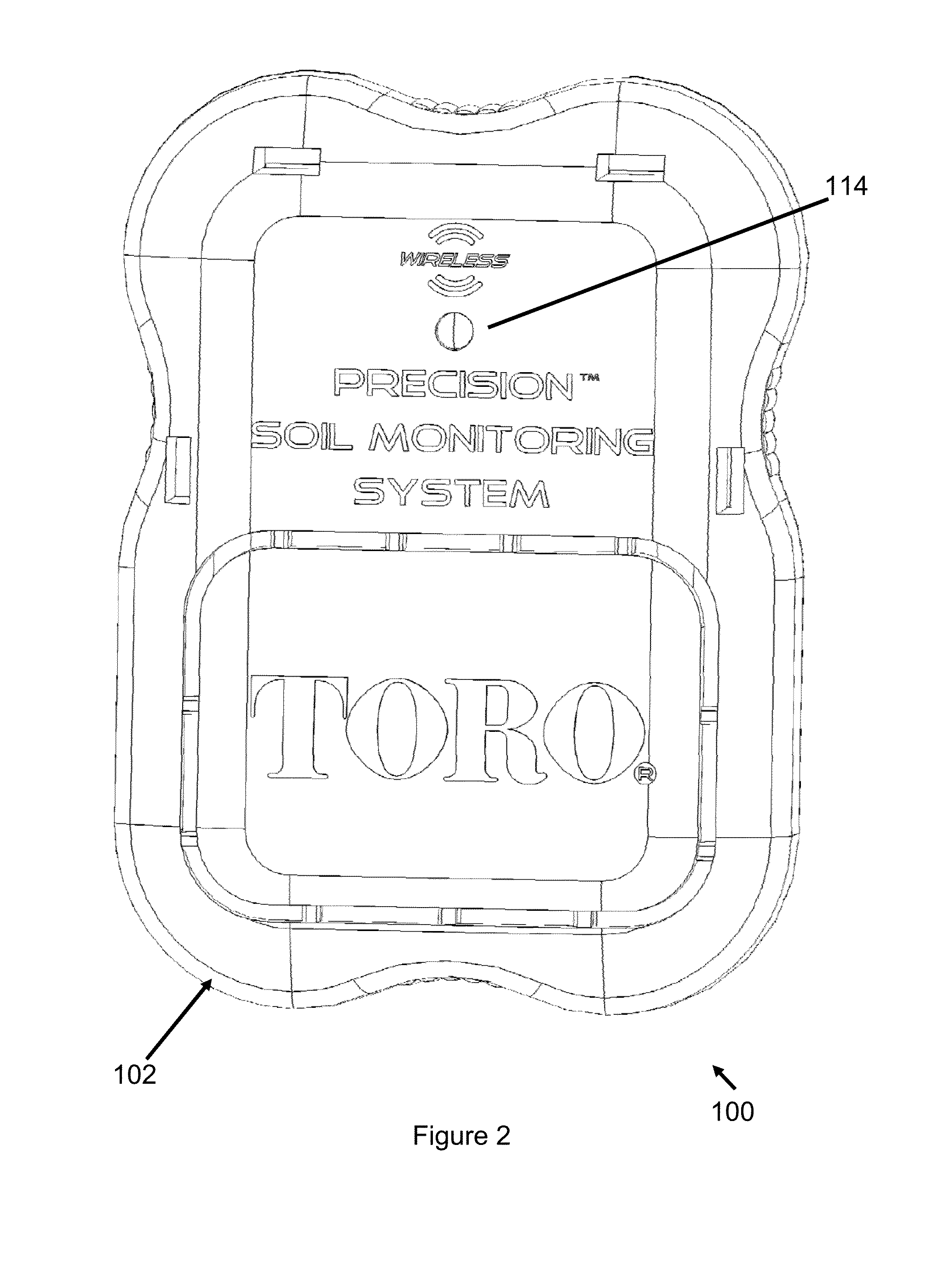
[0023]FIGS. 1-9 illustrate various views of a wireless soil moisture sensor 100 that communicates with a receiver unit 150, shown in FIG. 10 (also referred to as a soil moisture sensor interface). The moisture sensor 100 measures soil moisture, salinity, and temperature values of a region of soil at its ground location and periodically transmits these values t...


PUM


Abstract

In one embodiment, the present invention is directed to a soil moisture sensor for interrupting an irrigation schedule of an irrigation controller. The moisture sensor comprises a relatively flat body with two lower electrodes and two lower anchoring barbs. A receiver receives moisture readings from the sensor and compares moisture data to a predetermined moisture interrupt value or limit, over which irrigation is interrupted.

Description

RELATED APPLICATIONS[0001]This application claims priority to U.S. Provisional Application Ser. No. 61 / 550,817 filed Oct. 24, 2011 entitled Soil Moisture Sensor, which is hereby incorporated herein by reference in its entirety.BACKGROUND OF THE INVENTION[0002]Most common types of environmental monitoring and control for irrigation systems incorporate a means of controlling the start time and duration of watering cycles via a central timing controller. The need to adjust a watering cycle due to the environmental influence is necessary in order to save natural resources, reduce costs, and to improve the growing environment for plants. Such environmental conditions include temperature changes, relative humidity, precipitation, wind and cloud cover.[0003]In conventional control system, the primary means for halting an automatic watering cycle when certain environmental event occurs is by an operator manually suspending the cycle at the irrigation controller. In most situations this prov...

Claims


Application Information

Patent Timeline
IPC IPC(8): A01G25/16
CPCA01G25/167G08B21/20Y10T137/0318Y10T137/1866Y10T137/189
Inventor RUNGE, THOMAS H.HILL, JASON LESTERZIMMERMAN, JAMES
Owner TORO CO THE
Learn More