Developer container, developing device, process unit, and image forming apparatus

a technology of developing device and developer container, which is applied in the direction of electrographic process apparatus, instruments, optics, etc., can solve the problems of difficult downsizing of devices, and achieve the effect of improving the degree of freedom of design the layout of the container guide portion at the developer container and reducing the size of the developer container

Active Publication Date: 2013-10-03
RICOH KK
View PDF0 Cites 41 Cited by
  • Summary
  • Abstract
  • Description
  • Claims
  • Application Information

AI Technical Summary

Benefits of technology

[0012]In the above configuration, a gear in the sequence of the gears is movable between the operating position and the retracted position. Therefore, even if the part of or all the guide portion at the developer container is disposed within the projection area of the gear placed at the operating position, the main body side guiding portion at the image...

Problems solved by technology

Therefore, there is a problem that...

Method used


Image

  • Developer container, developing device, process unit, and image forming apparatus
  • Developer container, developing device, process unit, and image forming apparatus
  • Developer container, developing device, process unit, and image forming apparatus

Examples


first embodiment

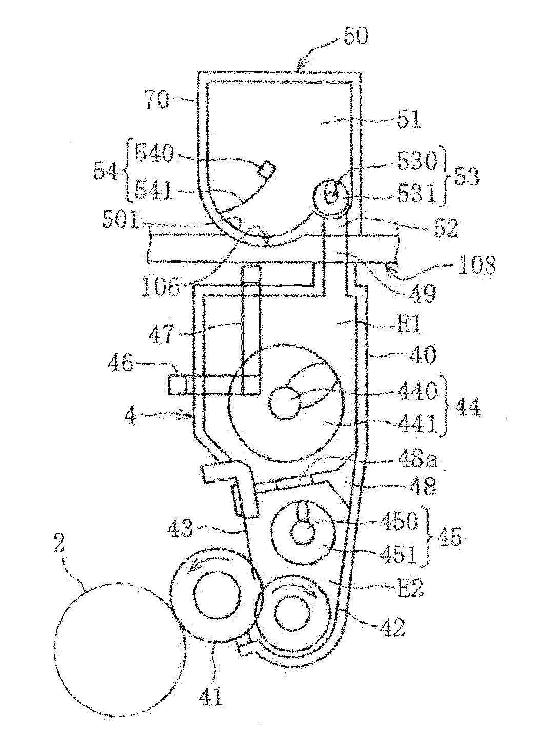
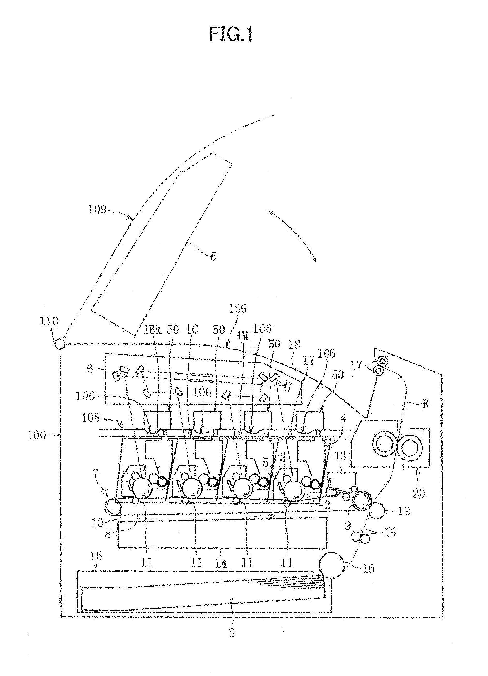
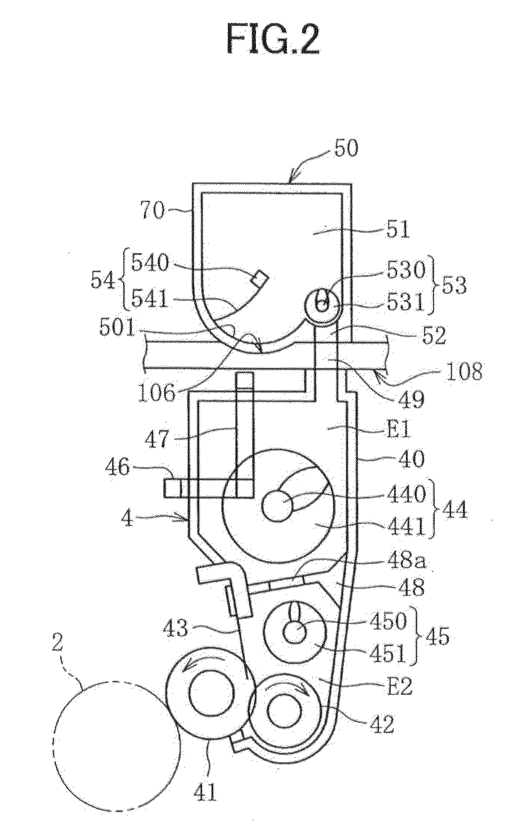
[0083]Hereinafter, an overall configuration and operations of a color laser printer according to a first embodiment of the present invention are explained by referring to FIG. 1. However, the embodiment of the present invention is not limited to this. The configuration according to the embodiment may be applied to a monochrome printer, other printers, a copier, a facsimile machine, and an image forming apparatus that is a combined machine thereof.

[0084]As shown in FIG. 1, four process units 1Y, 1M, 1C, and 1Bk are detachably attached to an apparatus main body of the color laser printer (image forming apparatus main body) 100 as image forming units. The process units 1Y, 1M, 1C, and 1Bk has the same configurations, except that the process unit 1Y stores yellow (Y) toner, the process unit 1M stores magenta (M) toner, the process unit 1C stores cyan (C) toner, and the process unit 1Bk stores black (Bk) toner. The different colors of yellow, magenta, cyan, and black correspond to color ...

second embodiment

[0203]FIGS. 30 through 33 show a configuration of the image forming apparatus according to a second embodiment. Hereinafter, portions of the image forming apparatus according to the second embodiment that are different from the corresponding portions of the image forming apparatus according to the first embodiment are explained.

[0204]As shown in FIG. 30, the image forming apparatus includes an upper cover 109 as a first cover that is disposed at an upper portion of the apparatus main body 100; a container mounting portion 120 on which the toner cartridges 50 can be mounted when the upper cover 109 is opened; an internal cover 116 as a second cover that is disposed inside the apparatus main body 100 (below the container mounting portion 120) and that is openable and closeable; and a unit mounting portion 130 to which the process units 1Y, 1M, 1C, and 1Bk can be detachably attached when the internal cover 116 is opened. FIG. 31 shows a state of the image forming apparatus where the up...


PUM


Abstract

The developer container includes a rotator that is rotated in the container body, a sequence of gears disposed outside the developer container that transmits a torque to the rotator, and a container guiding portion that fits with a main body side guiding portion and guides the developer container in a direction in which the developer container is attached to a mounting portion of an image forming device main body. A first gear included in the sequence of the gears is movable between an operating position where the first gear engages with a second gear and a retracted position where the first gear is retracted. On a surface on which the container guiding portion is disposed, a part of the container guiding portion is disposed within a projected area of the first gear being disposed at the operating position.

Description

CROSS-REFERENCE TO RELATED APPLICATIONS[0001]This application is a U.S. continuation application filed under 35 USC 111a and 365c of PCT application JP2012 / 069783, filed on Jul. 27, 2012, which claims priority to Applications Ser. No. 2011-164036, filed in Japan on Jul. 27, 2011, Ser. No. 2012-019940, filed in Japan on Feb. 1, 2012, and Ser. No. 2012-019937, filed in Japan on Feb. 1, 2012.[0002]The foregoing applications are hereby incorporated by reference in their entirety.TECHNICAL FIELD[0003]Embodiments of the present invention relate to a developer container that contains developer, a developing device, a process unit, and an image forming apparatus that include the developer container.BACKGROUND ART[0004]For an image forming apparatus, such as a copier, a printer, a facsimile, and a compound machine thereof, a scheme has been known such that, for example, a developing device, a charging device, and a photoconductor are integrally formed as an image forming unit, and the image ...

Claims


Application Information

Patent Timeline
IPC IPC(8): G03G15/08
CPCG03G21/1676G03G15/0889G03G21/1647G03G15/0886G03G15/0865G03G15/0891G03G15/0896G03G21/18G03G15/08
Inventor KUBOTA, TOMOHIRONAKATAKE, NAOKISHIMIZU, YOSHIYUKITSURITANI, SHOHHAMADA, MANABUTSUJI, MASATOFUJITA, MASANARI
Owner RICOH KK
Why Eureka
Try Eureka