Manual surgical ligation clip applier

Active Publication Date: 2013-10-03
TELEFLEX MEDICAL INC
View PDF3 Cites 27 Cited by
  • Summary
  • Abstract
  • Description
  • Claims
  • Application Information

AI Technical Summary

Benefits of technology

[0019]In a seconded embodiment of the invention; the clip is positioned over the vessel with actuation of the wedge and catch mechanism and is subsequently closed when a punch mechanism is engaged with the locking feature on the clip. The features of the clip lock cause the legs of the clip to close and once fully locked the clip maintains the clamping pressure on the vessel.
[0020

Problems solved by technology

The use of surgical thread for ligation requires complex manipulations of the needle and suture material to form the knots required to secure the vessel.
Such complex manipulations are time-consuming and difficult to perform, particularly in endoscopic surgical procedures, which are characterized by limited space and visibility.
But, with the advent of high technology diagnostic techniques using computer tomography (CATSCAN) and magnetic resonance imaging (MRI), metallic clips have been found to interfere with the imaging techniques.
However this clip is: (i) rudimentary in construction, (ii) does not provide adequate clip closing or clamping strength, (iii) lacks any complex geometry which would adequately retain the clip in a closed position, and further (iv) is too unstable when closed to

Method used


Image

  • Manual surgical ligation clip applier
  • Manual surgical ligation clip applier
  • Manual surgical ligation clip applier

Examples


first embodiment

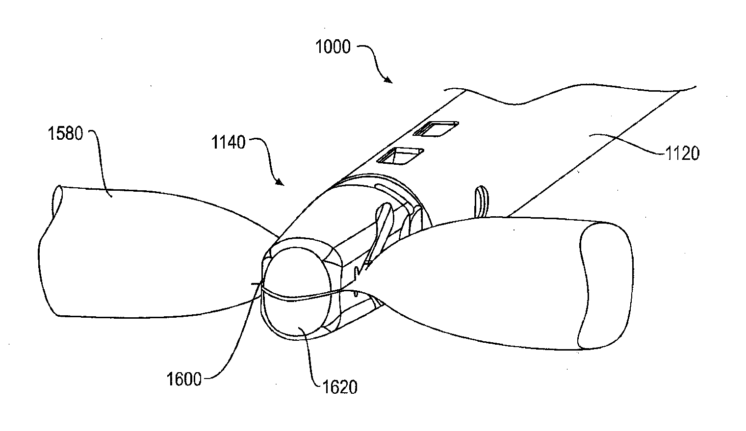
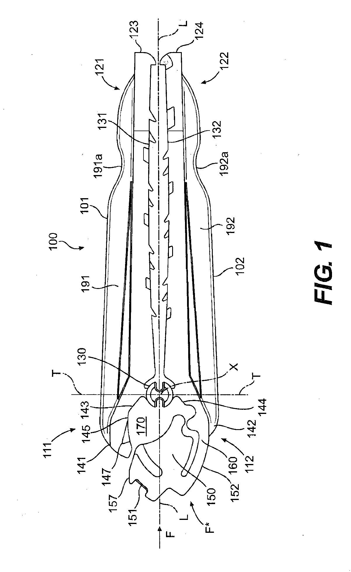
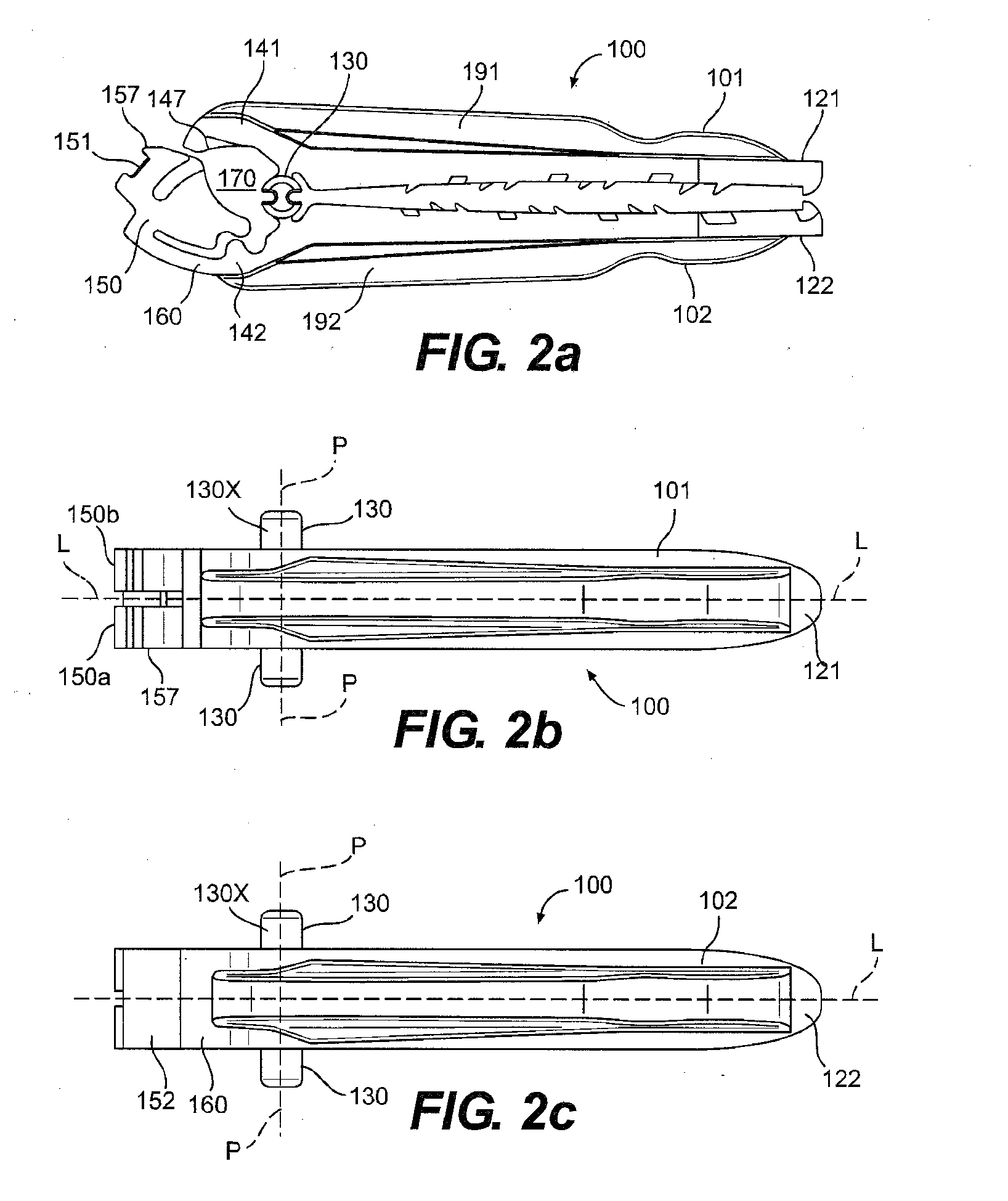
[0148]FIG. 1 shows a view of a surgical ligation clip 100 in accordance with present invention. The clip 100 defines a longitudinal axis “L” along its longest dimension and includes a first leg 101 and a second leg 102 each extending along the longitudinal axis L and having proximal 111, 112 and distal 121, 122 end portions with respect to said longitudinal axis. As used herein, the term “proximal” shall refer to the portion of the clip referenced herein which is away from the tips of the clip which open, and “distal” shall refer to the portion of the clip at the tips which open, in accordance with the convention that the clip is inserted distal tip first through an instrument towards an anatomical body to be ligated, such that distal generally refers to the direction away from the user or applier of the surgical clip and proximal refers to the direction opposite to distal.

[0149]In clip 100, a clip hinge 130 joins the first and second legs 101, 102 at a point on their respective pro...

second embodiment

[0192]In the invention the wedges and catches are separate pieces attached to a catch tube, see FIGS. 60-63, and have the same forward actuation sequence as the 1st embodiment to lock the clip but does not require a dwell on the punch when the punch returns to the start position. In this embodiment the wedge and catch assembly stop just short of the clip stopping on the inner end surface of the jaws. The punch is then pushed forward to engage with the locking feature of the clip. The clip is first pushed out of the catch and wedges until the legs of the clip stop on the inner end surface of the jaws. The punch continues forward forcing the locking mechanism on the clip to rotate into the clip's locked position. During the rotation of the locking mechanism of the clip the legs are clamped together with the locking mechanism instead of the wedges as previously described. This embodiment also has internal leaf springs attached to the inner tube that bias the ends of the wedges together...


PUM


Abstract

A ligation clip applier is provided. The clip applier includes: a pair of jaws; a distal clevis tube to which the jaws are pivotally mounted; a proximal clevis tube located behind the distal clevis tube, wherein the distal clevis tube and the proximal clevis tubes move axially with respect to each other; a clip lock actuator fixed to one of the proximal and distal clevis tubes; and a distal pushrod extending through the distal and proximal clevis tubes and forming a camming connection with the jaws configured to close and move the jaws toward a proximal direction toward the clip lock actuator when the distal pushrod is moved in the proximal direction. A method for applying a clip on a vessel is disclosed.

Description

CROSS-REFERENCE TO RELATED APPLICATIONS[0001]This application claims priority to pending provisional U.S. patent application entitled, Manual Surgical Ligation Clip Applier, filed Sep. 15, 2011, having a Ser. No. 61 / 535,190, the disclosure of which is hereby incorporated by reference in its entirety.FIELD OF THE INVENTION[0002]The present invention relates to medical devices and in particular a device for applying surgical clips for ligation of vessels or tissue.BACKGROUND[0003]Many surgical procedures require vessels or other fluid ducts or tissue conduits and structures to be ligated during the surgical process, such as, for example, veins or arteries in the human body. For example, many surgical procedures require cutting blood vessels, and these blood vessels may require ligation to reduce bleeding. In some instances, a surgeon may wish to ligate the vessel temporarily to reduce blood flow to the surgical site during the surgical procedure. In other instances a surgeon may wish ...

Claims


Application Information

Patent Timeline
IPC IPC(8): A61B17/128
CPCA61B17/128A61B17/122A61B17/1285A61B17/12A61B90/03A61B17/1222A61B2017/12004
Inventor WILLETT, LYNNSCHMIDT, PHILIPMONAHAN, DANLEHMAN, ADAMADAMS, LELAND RAYWHITING, PAULCASTRO, SALVATOREBACHMAN, ADAM
Owner TELEFLEX MEDICAL INC
Why Eureka
Try Eureka