Clamping unit and chuck unit of clamping device

A chuck and clamping cylinder technology, applied in the field of clamping units, can solve problems such as operator danger, damage to processing machinery, etc., and achieve the effect of improving safety

Active Publication Date: 2017-05-31
海勒机械制造兄弟有限公司
View PDF11 Cites 1 Cited by
  • Summary
  • Abstract
  • Description
  • Claims
  • Application Information

AI Technical Summary

Problems solved by technology

Unintentional loosening or loosening of the workpiece in the chuck unit can caus

Method used


Image

  • Clamping unit and chuck unit of clamping device
  • Clamping unit and chuck unit of clamping device
  • Clamping unit and chuck unit of clamping device

Examples


Embodiment Construction

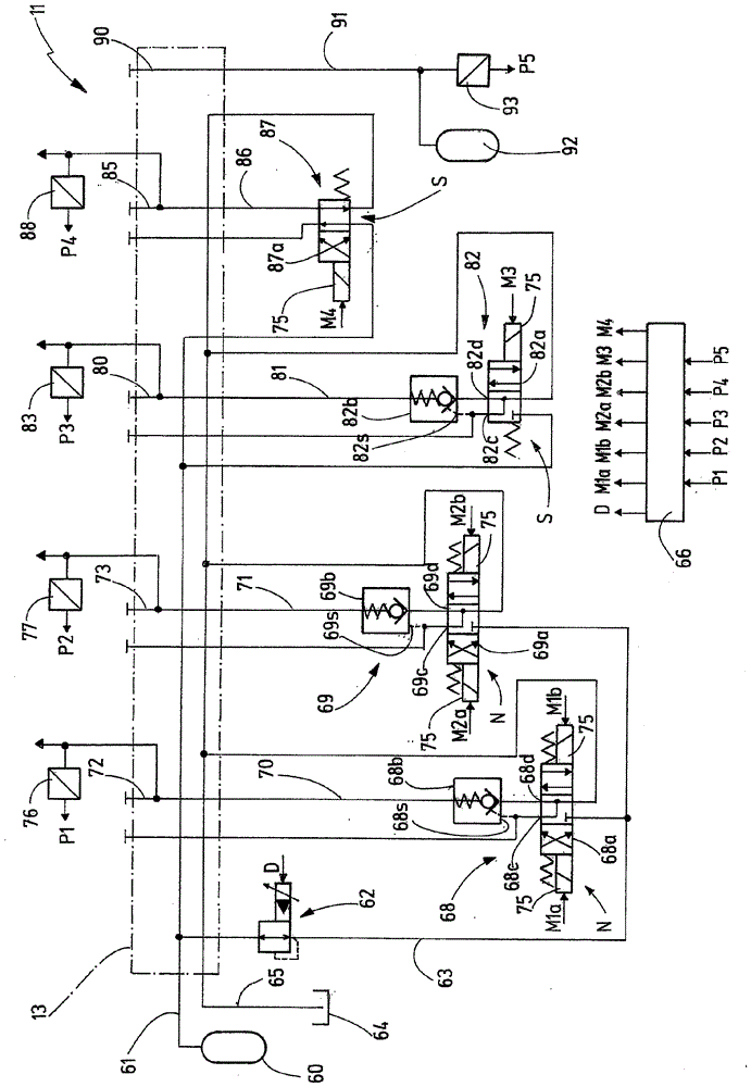
[0044] exist figure 1 A clamping device 10 with a clamping unit 11 and a chuck unit 12 is schematically shown in . The clamping unit 11 and the chuck unit 12 are fluidly and mechanically connectable to each other. For this purpose, the clamping unit 11 has a connecting device 13 and the chuck unit has a coupling device 14 , which cooperate in order to establish a mechanical and fluid connection.

[0045] A workpiece 15 can be clamped and held via the chuck unit 12 . The chuck unit 12 has clamping jaws 19 that are movable towards and away from each other. Preferably, the clamping jaws 19 are movable radially inwards or outwards relative to the longitudinal center axis of the chuck unit 12 in a common plane. The chuck unit 12 can have a carrier plate 25 , which carries the chuck unit 12 and is interposed, in particular for the mechanical connection, when establishing a connection with the clamping unit 11 . For manual operation, the carrier plate 25 is detachably connected t...


PUM


Abstract

The invention relates to a clamping device (10) which consists of a machine-side clamping unit (11) and a chuck unit (12) which can be mechanically and fluidically connected to the clamping unit. The chuck unit (12) has a clamping cylinder (20), which is provided for moving clamping jaws (19) and one working chamber (23) of which is fluidically connected to a first chuck connection (28) via a first clamping cylinder line (30) and the other working chamber (24) of which is fluidically connected to a second chuck connection (29) via a second clamping cylinder line (31). Each of the two clamping cylinder lines (30, 31) is equipped with a releasable non-return valve (36, 37) which is released when hydraulic medium is to be discharged from the corresponding working chamber (23) or (24). When the chuck unit (12) and the clamping unit (11) are fluidically connected, the two clamping cylinder lines (30, 31) are fluidically connected to paired hydraulic lines (70) and (71), respectively. Each hydraulic line (70, 71) is paired with a separately actuatable and switchable working valve device (68, 69). A movement of the clamping jaws (19) is only possible when each working valve device (68, 69) is switched from the neutral position N to a defined switch position (Z) or (R) via a control unit (66).

Description

technical field [0001] The invention relates to a clamping unit, a chuck unit fluidly and mechanically connectable to the clamping unit, a clamping device consisting of the clamping unit and the chuck unit, and clamping pliers for implementing the chuck unit method of clamping or loosening motion. Background technique [0002] In some applications for machining workpieces, the workpieces are clamped into chucking units and prepared, for example, at an assembly space for machining. In this case, the chuck unit is fluidly and mechanically connected to the clamping unit of the assembly space in order to move the clamping jaws of the chuck unit and clamp the workpiece internally or externally. The chuck unit also maintains the clamping force after the chuck unit is separated from the clamp unit. In this way, the workpiece can be transported from the assembly space to the processing machine in the clamped state and connected there again to the clamping unit of the processing ma...

Claims


Application Information

Patent Timeline
IPC IPC(8): B23Q1/00B23Q3/08B25B5/06B25B5/16
CPCB25B5/061B23Q1/0018B23Q3/082B25B5/16
Inventor L.费茨纳P.霍尔德R.克诺尔普
Owner 海勒机械制造兄弟有限公司
Why Eureka
Try Eureka