
Signal selecting circuit and signal selecting method

Inactive Publication Date: 2013-10-10
NEC CORP
View PDF2 Cites 6 Cited by
  • Summary
  • Abstract
  • Description
  • Claims
  • Application Information

AI Technical Summary

Benefits of technology

This patent describes a circuit and method for selecting signals without interrupting the output. The circuit detects abnormalities in the signals and can switch to a new signal without causing any sudden interruption. This allows for a smoother and more efficient operation of the system.

Problems solved by technology

However, in such PLL circuits, there is a problem that since it is necessary to use a circuit(s) including a large number of components such as a VCO and an APC circuit that controls the synchronization of the VCO, the circuit size increases.

Method used


Image

  • Signal selecting circuit and signal selecting method
  • Signal selecting circuit and signal selecting method
  • Signal selecting circuit and signal selecting method

Examples


Embodiment Construction

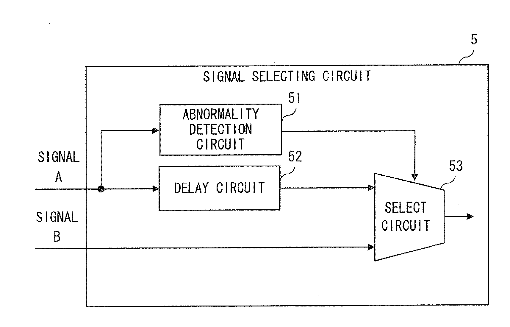
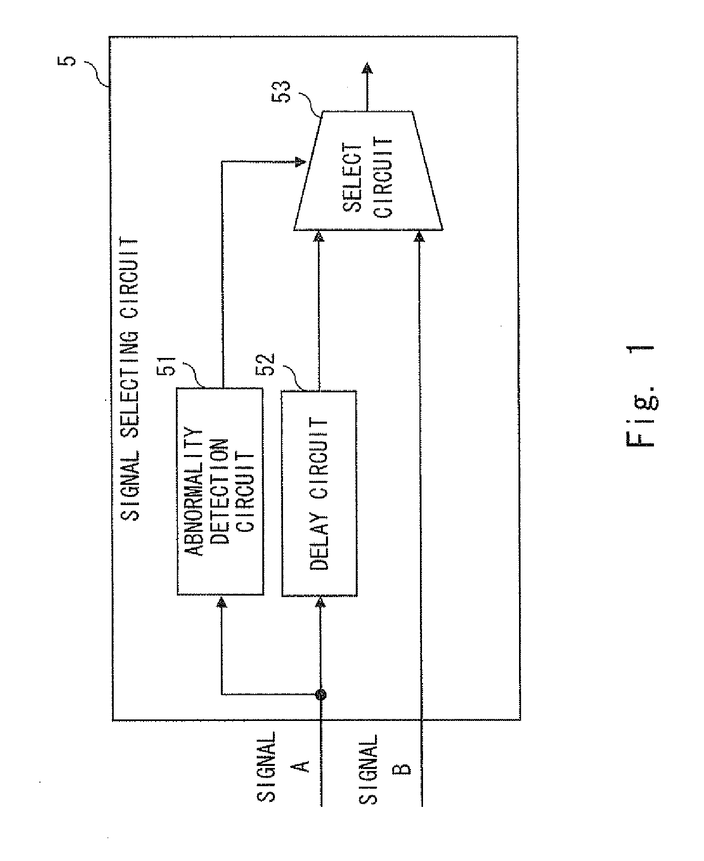
[0019]Firstly, a signal selecting circuit 5, which represents an outline of a clock switching circuit according to an exemplary embodiment of the present invention, is explained with reference to FIG. 1. FIG. 1 is a configuration diagram of a signal selecting circuit 5 according to an exemplary embodiment of the present invention.

[0020]The signal selecting circuit 5 includes an abnormality detection circuit 51, a delay circuit 52, and a select circuit 53. The signal selecting circuit 5 receives an arbitrarily-selected signal among a plurality of externally-supplied signals as a main signal and receives another signal as a reserve signal. The signal selecting circuit 5 selects and outputs the main signal in a normal state.

[0021]The abnormality detection circuit 51 detects an abnormality of the signal input as the main signal in an input stage.

[0022]The delay circuit 52 delays the signal input as the main signal by a delay time that is equal to or greater than the total time of a dete...


PUM


Abstract

A signal selecting circuit according to the present invention includes an abnormality detection circuit that detects an abnormality of the signal input as the main signal in an input stage, a select circuit that selects and outputs the signal input as the main signal among the plurality of signals in the normal state, and when the abnormality detection circuit detects an abnormality of the signal input as the main signal, selects and outputs the signal input as the reserve signal, and a delay circuit that delays the signal input as the main signal by a delay time and outputs the delayed signal to the select circuit, the delay time being equal to or greater than a total time of a detection time in the abnormality detection circuit and a signal switching time in the select circuit.

Description

TECHNICAL FIELD[0001]The present invention relates a signal selecting circuit and a signal selecting method.BACKGROUND ART[0002]There is a type of PLL (Phase Locked Loop) circuit that includes a VCO (Voltage controlled Oscillator) and an APC (Automatic Power Control) circuit that controls an APC signal for the VOC. An example of such a PLL circuit is disclosed in Patent literature 1. In such PLL circuits, the APC circuit controls the VOC so that a clock signal whose frequency is in synchronization with a clock signal supplied from a clock source is generated and output.[0003]Further, in a PLL circuit having a VCO and an APC circuit as described above, it is possible to continue to generate a clock signal even when the supply of the clock signal from the clock source is stopped. That is, in a PLL circuit having a VCO and an APC circuit, it is possible to equip the PLL circuit with a holdover function that makes it possible to continue to generate a signal even when the supply of a ba...

Claims


Application Information

Patent Timeline
IPC IPC(8): H04L7/00H04L69/14H04L69/40
CPCG06F1/04H04L7/0337H04L7/0037H04B1/74
Inventor TAZAKI, YUICHI
Owner NEC CORP
Learn More