
Method and apparatus for estimating cross-phase modulation impairments

Active Publication Date: 2013-10-10
FUJITSU LTD
View PDF1 Cites 11 Cited by
  • Summary
  • Abstract
  • Description
  • Claims
  • Application Information

AI Technical Summary

Benefits of technology

The technical effect of this patent is to provide a way to quickly and accurately estimate cross-phase modulation (XPM) impairments caused by polarization mode dispersion. This allows for better understanding and mitigation of these impairments in optical network systems.

Problems solved by technology

Phase noise and polarization crosstalk resulted from the cross-phase modulation are one of the main sources leading to the cost of a dense wavelength division multiplexing system.
However, the SSF simulation is very time-consuming and the number of time windows and channels which can be studied is very limited; and the transmission experiment needs to spend a lot of manpower and material resources.
However, polarization mode dispersion is not taken into consideration in these methods, while the polarization mode dispersion does exist in a practical fiber transmission system.

Method used


Image

  • Method and apparatus for estimating cross-phase modulation impairments
  • Method and apparatus for estimating cross-phase modulation impairments
  • Method and apparatus for estimating cross-phase modulation impairments

Examples


embodiment 1

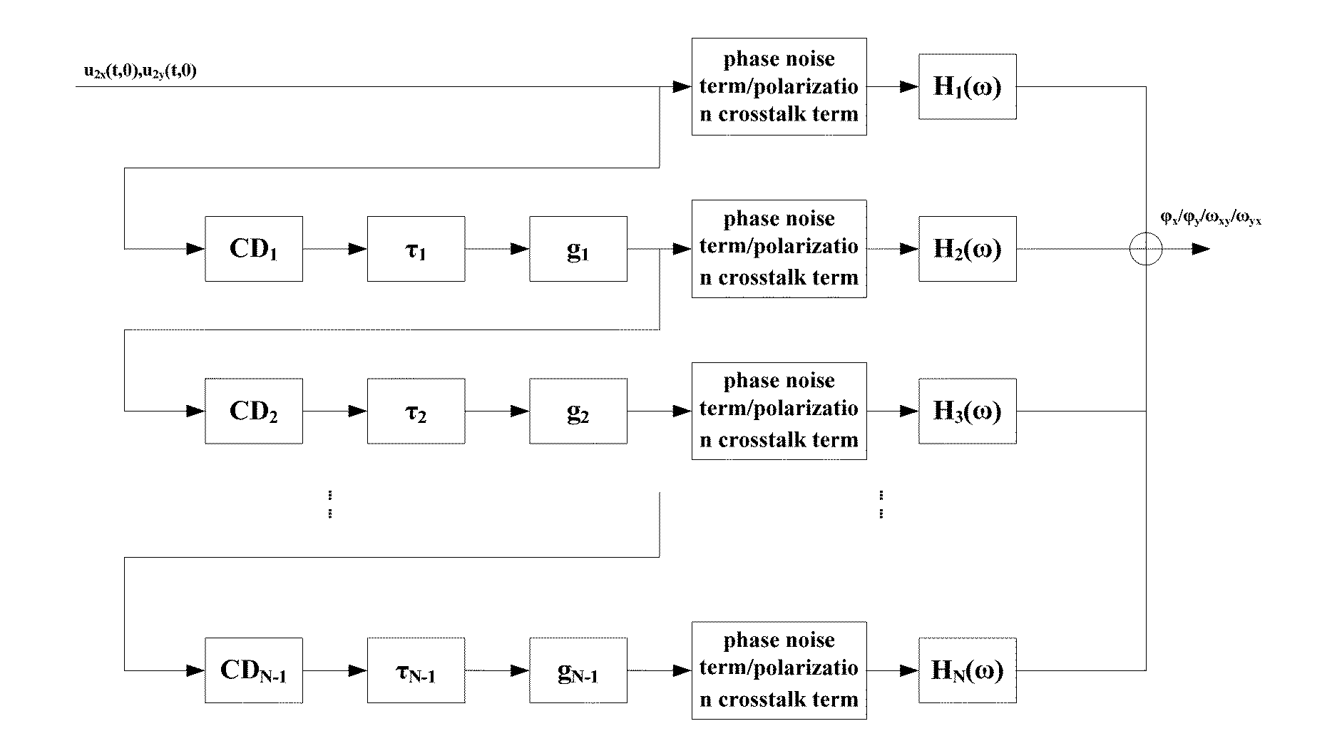
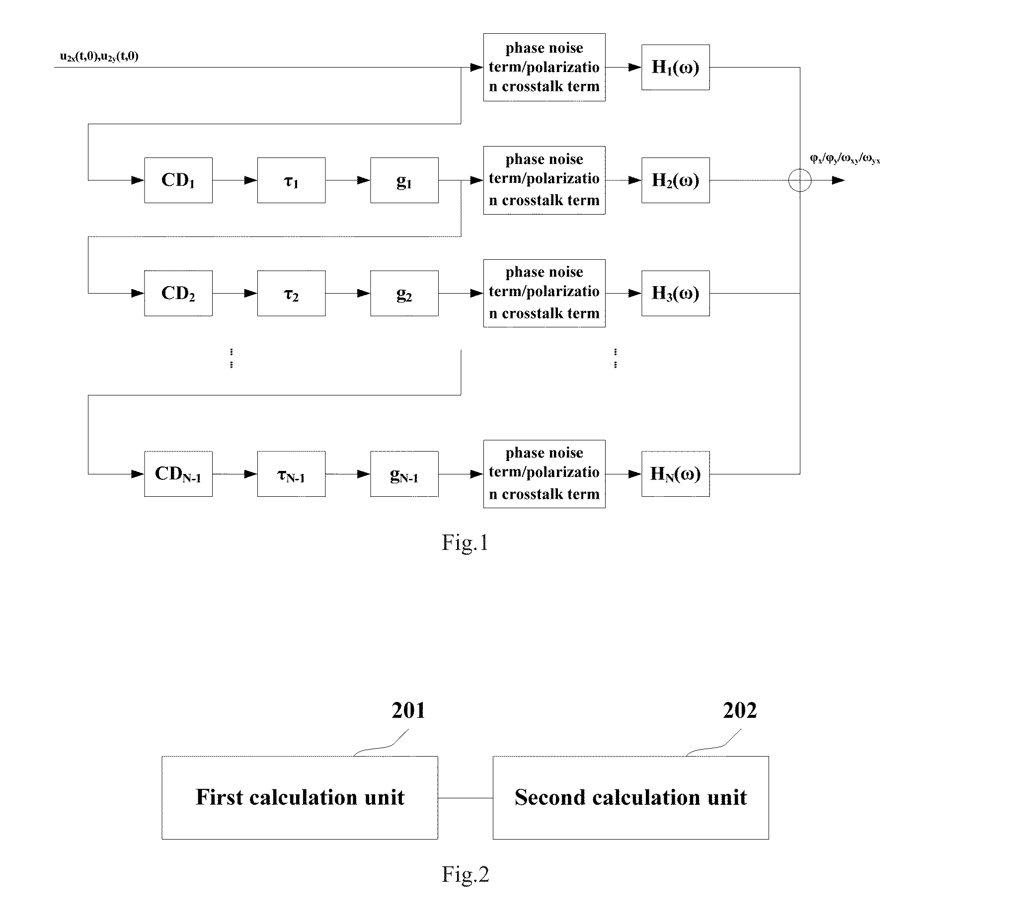
[0042]An embodiment of the present invention provides an apparatus for estimating cross-phase modulation (XPM) impairments. FIG. 2 is a schematic diagram of the composition of the apparatus; referring to FIG. 2, the apparatus comprises:

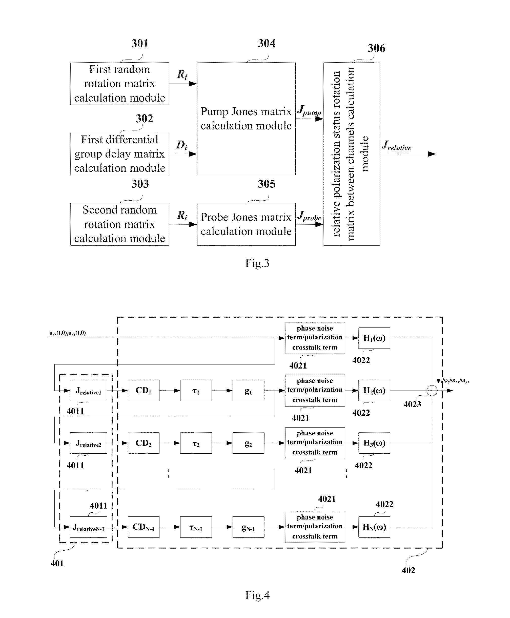
[0043]a first calculation unit 201 for calculating, according to a pump Jones matrix of a pump channel and a probe Jones matrix of a probe channel of each of fiber spans except for the first fiber span in a fiber transmission system, a polarization mode dispersion (PMD)-induced relative polarization status rotation matrix between channels of the each of fiber spans; and

[0044]a second calculation unit 202 for calculating, according to the relative polarization status rotation matrix of the each of fiber spans, dispersion of a pump signal of the each of fiber spans, differential delay of the pump signal relative to a probe signal of the each of fiber spans and a gain of the each of fiber spans, polarization crosstalk and phase noise of the XPM impairmen...

embodiment 2

[0093]An embodiment of the present invention further provides a method for estimating cross-phase modulation (XPM) impairments. FIG. 5 is a flowchart of the method; referring to FIG. 5, the method comprises:

[0094]step 501: determining, according to a pump Jones matrix of a pump channel and a probe Jones matrix of a probe channel of each of fiber spans except for the first fiber span in a fiber transmission system, a polarization mode dispersion (PMD)-induced relative polarization status rotation matrix between channels of the each of fiber spans; and

[0095]step 502: determining, according to the relative polarization status rotation matrix of the each of fiber spans, dispersion of a pump signal of the each of fiber spans, differential delay of the pump signal relative to a probe signal of the each of fiber spans and a gain of the each of fiber spans, polarization crosstalk and phase noise of the XPM impairments in the fiber transmission system.

[0096]In an example of step 501, particu...


PUM


Abstract

A system for estimating cross-phase modulation (XPM) impairments, wherein the method comprises: determining, according to a pump Jones matrix of a pump channel and a probe Jones matrix of a probe channel of each of fiber spans except for the first fiber span in a fiber transmission system, a polarization mode dispersion (PMD)-induced relative polarization status rotation matrix between channels of the each of fiber spans; and determining, according to the rotation matrix of the each of fiber spans, dispersion of a pump signal of the each of fiber spans, differential delay of the pump signal relative to a probe signal of the each of fiber spans and a gain of the each of fiber spans, polarization crosstalk and phase noise of the XPM impairments in the fiber transmission system. This allows the XPM impairments in the effect of the polarization mode dispersion to be quickly and accurately estimated,

Description

CROSS-REFERENCE TO RELATED APPLICATION[0001]This application is based upon and claims the benefit of priority of the prior Chinese Patent Application No. 201210100071.X, filed on Apr. 6, 2012, the entire contents of which are incorporated herein by reference.TECHNIACL FIELD[0002]The present invention relates to the fiber communications and, in particular, to a method and an apparatus for estimating cross-phase modulation (XPM) impairments in the effect of polarization mode dispersion.BACKGROUND ART[0003]Phase noise and polarization crosstalk resulted from the cross-phase modulation are one of the main sources leading to the cost of a dense wavelength division multiplexing system. Traditional methods for researching the XPM comprise Split Step Fourier (SSF) simulation and a transmission experiment. However, the SSF simulation is very time-consuming and the number of time windows and channels which can be studied is very limited; and the transmission experiment needs to spend a lot of...

Claims


Application Information

Patent Timeline
IPC IPC(8): H04B10/2557
CPCH04B10/2569H04B10/2557
Inventor CAO, YINWENYAN, WEIZHENTAO, ZHENNING
Owner FUJITSU LTD
Learn More