Hand held appliance

Active Publication Date: 2013-10-17
DYSON TECH LTD
View PDF6 Cites 57 Cited by
  • Summary
  • Abstract
  • Description
  • Claims
  • Application Information

AI Technical Summary

Benefits of technology

[0059]A further advantage to having a fan assembly which process some of the fluid flow through the hairdryer and having a fluid flow which is partially drawn and partially entrained is that the ducts through which the processed fluid flows can be of a relatively small diameter. For example for an outflow from the body of around 25 l/s, something like 10 to 12 l/s passes through the ducts and this flow has a maximum velocity of around 25 m/s. As the ducting has a smaller diameter than would be required for full processing of the fluid, silencing of noise produced by the fluid flow through the primary fluid flow path is effective over a larger range of frequencies than for a larger diameter duct. Thus, airborne noise is attenuated to a higher frequency. This is because a duct diameter of less than around half a wavelength promotes planar wave behaviour.
[0060]It is preferred that a filter is provided for filtering one of the two fluid flow paths. Preferably, the filter filters the primary fluid

Problems solved by technology

The motor is susceptible to damage from foreign objects such as dirt or hair

Method used


Image

  • Hand held appliance
  • Hand held appliance
  • Hand held appliance

Examples


Embodiment Construction

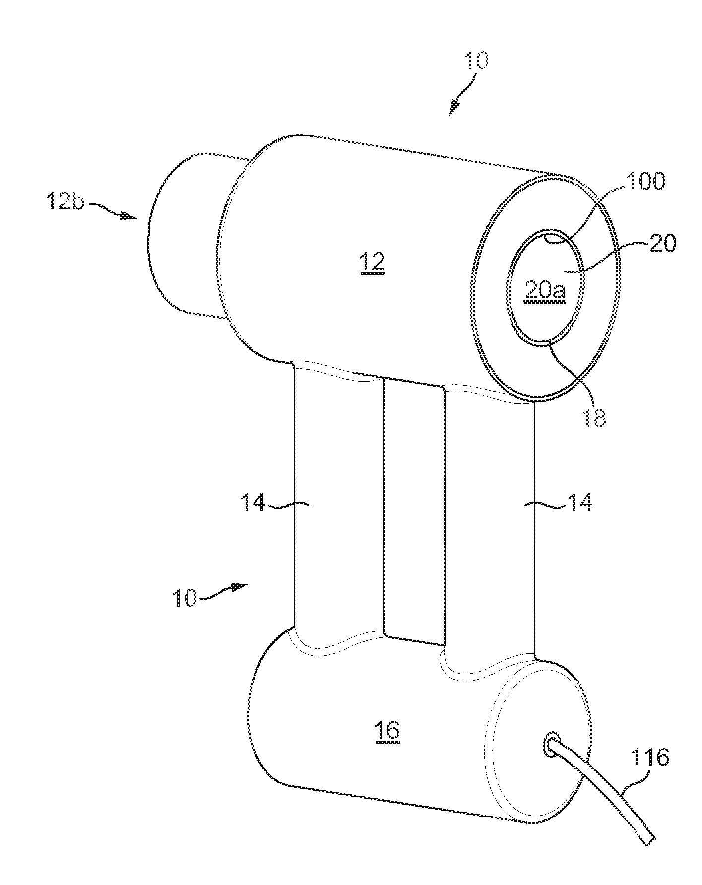
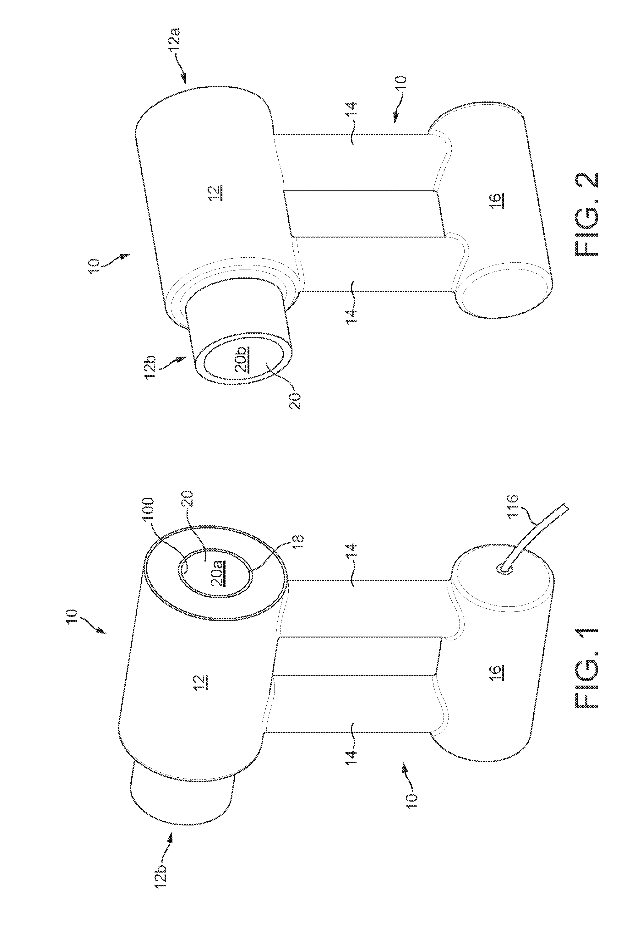
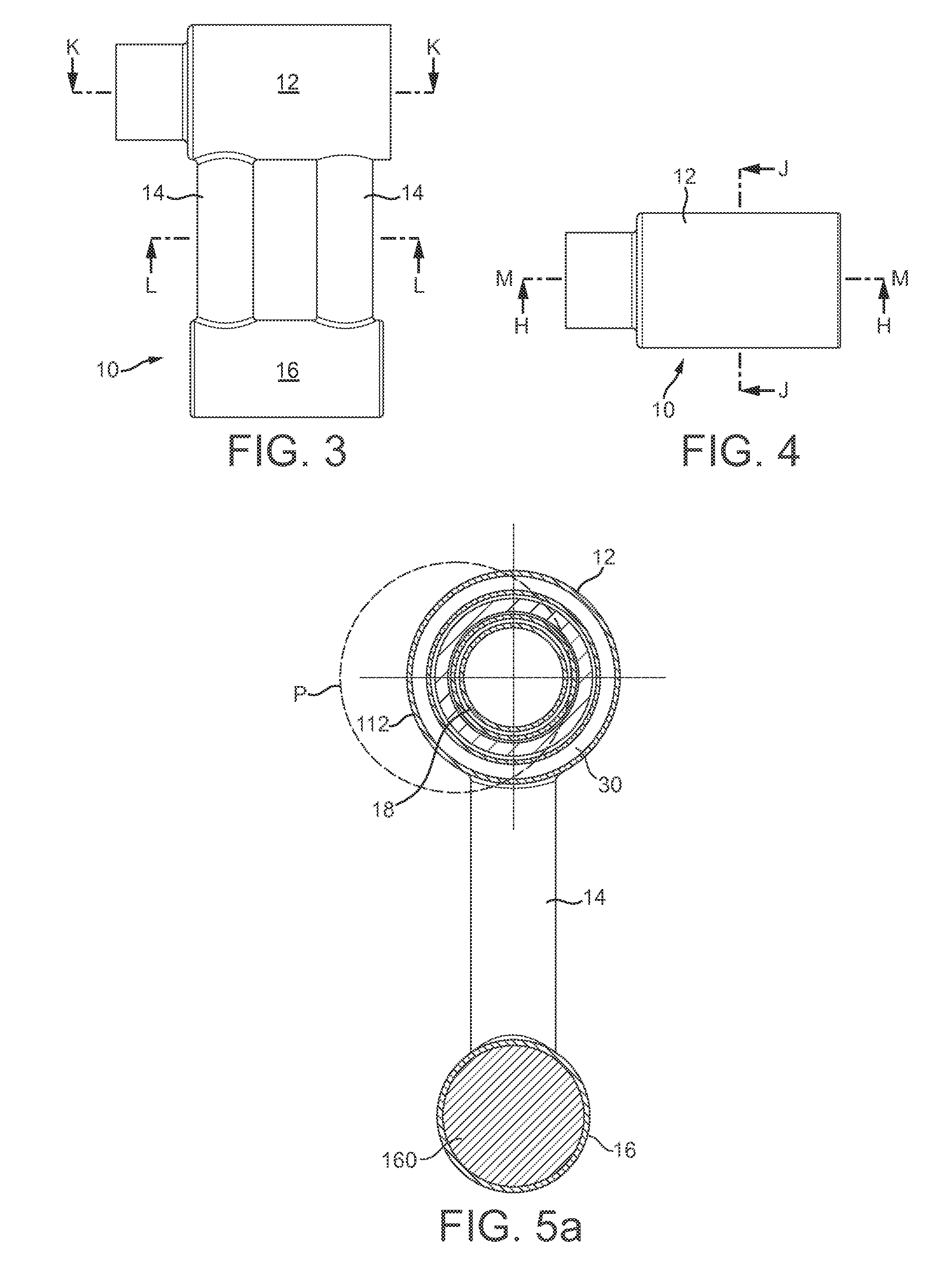
[0111]FIGS. 1 to 4 show various views of an appliance 10 having a first body 12 which defines a fluid flow path 20 through the appliance and a pair of ducts 14 which extend from the first body 12 to a second body 16. The fluid flows through the appliance from an inlet or upstream end to an outlet or downstream end.

[0112]With reference to FIGS. 5a, 5b, 5c and 6, the fluid flow path 20 has a fluid intake 20a at a rear end 12a of the body 12 and a fluid outflow 20b at a front end 12b of the body 12. Thus, fluid can flow along the whole length of the body 12. The fluid flow path 20 is a central flow path for the body 12 and for at least a part of the length of the body 12 the fluid flow path is surrounded and defined by a tubular housing 18. The tubular housing 18 is a bore, pipe or conduit that the generally longer that it is wide and preferably has a substantially circular cross section, however, it may be oval, square, rectangular or another shape. The first body is tubular in shape....


PUM


Abstract

A hand held appliance, such as a hairdryer, includes a body having a fluid inlet for admitting fluid into the appliance, a fluid outlet, a duct lined with a material, and a primary fluid flow path extending from the fluid inlet to the fluid outlet and through the duct. The material may be a foam or a felt and is a sound absorbing material, a vibration absorbing material, is an insulator, is tuned to resonant frequencies of the appliance. The primary fluid flow path may be non-linear. The duct may have a non-circular cross-section and may comprise a handle portion of the appliance, and the handle portion of the duct is lined with said material. A fan unit may be provided located upstream of the handle portion. The duct may comprise a first handle portion and a second handle portion of the appliance.

Description

REFERENCE TO RELATED APPLICATIONS[0001]This application claims the priority of United Kingdom Application No. 1205679.2, filed Mar. 30, 2012, the entire contents of which are incorporated herein by reference.FIELD OF THE INVENTION[0002]This invention relates to a blower and in particular a hot air blower such as a hairdryer.BACKGROUND OF THE INVENTION[0003]Blowers and in particular hot air blowers are used for a variety of applications such as drying substances such as paint or hair and cleaning or stripping surface layers. Generally, a motor and fan are provided which draw fluid into a body; the fluid may be heated prior to exiting the body. The motor is susceptible to damage from foreign objects such as dirt or hair so conventionally a filter is provided at the fluid intake end of the blower.SUMMARY OF THE INVENTION[0004]The present invention provides a hairdryer comprising a body, a fan unit and a duct for conveying fluid to the body, wherein the duct comprises a fluid inlet loca...

Claims


Application Information

Patent Timeline
IPC IPC(8): A45D20/04
CPCA45D20/04A45D20/10A45D20/12F24H3/0423
Inventor COURTNEY, STEPHEN BENJAMINMOLONEY, PATRICK JOSEPH WILLIAMGAMMACK, PETER DAVID
Owner DYSON TECH LTD
Why Eureka
Try Eureka