Tiled display rotational assembly

Active Publication Date: 2013-10-17
CHRISTIE DIGITAL SYST USA INC
View PDF7 Cites 63 Cited by
  • Summary
  • Abstract
  • Description
  • Claims
  • Application Information

AI Technical Summary

Benefits of technology

[0007]It is an aspect of the present invention to provide a

Problems solved by technology

When a tiled display is being used as one large display, having even a single individual display out of alignment can ruin the image.
Typically, installing a tiled display is difficult and pre

Method used


Image

  • Tiled display rotational assembly
  • Tiled display rotational assembly
  • Tiled display rotational assembly

Examples


Example

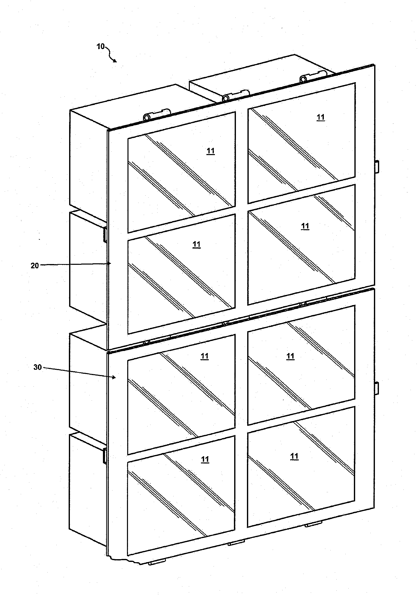
[0022]FIG. 1 is a perspective view of the front of a tiled display mounting system 10 with displays 11 in place. The tiled display mounting system 10 is shown assembled and ready for use. More specifically, first panel 20 and second panel 30 are linked together in the locked position (explained below with reference to FIGS. 3-7).

[0023]Each of panels 20, 30, as shown, is configured to mount a 2×2 array of displays 11. Those skilled in the art will recognize that panels 20, 30 may be configured to mount an array of displays 11 of any convenient dimensions, and that manufacturing the panels 20, 30 to a predetermined configuration and pre-mounting at least some of the individual displays 11, the difficulty of aligning individual displays 11 on-site is avoided and the overall set-up time is also shortened.

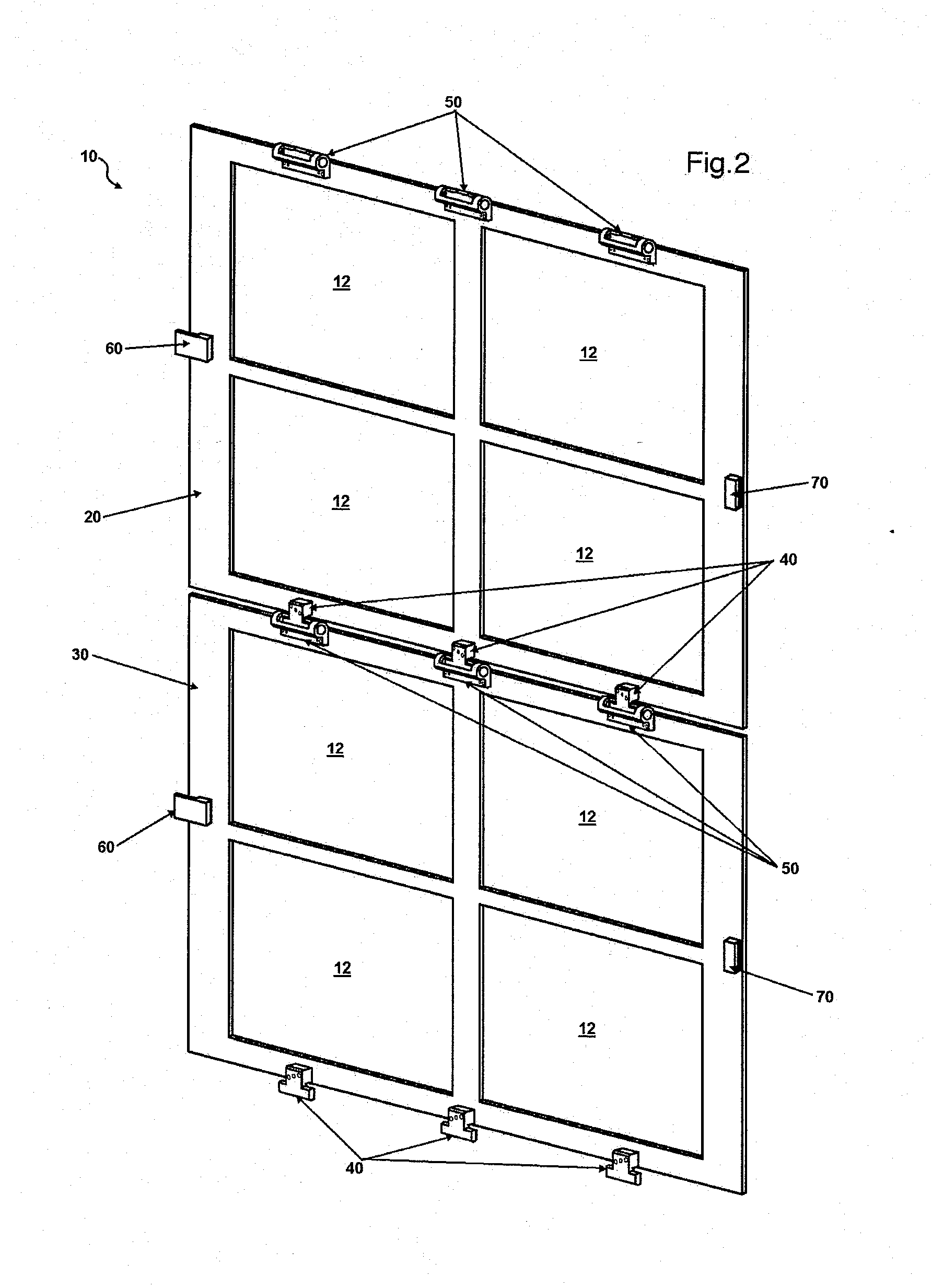
[0024]FIG. 2 is a perspective view of the back of a tiled display mounting system 10 with displays removed. More specifically, extending hinge portions 40 have been inserted into receiv...


PUM


Abstract

A tiled display rotational assembly is provided. The system uses panels connected by hinges, the panels configured to mount at least one display on each panel. A first panel has an extending hinge portion with a first bearing surface attached to an edge while a second panel has a receiving hinge portion with a second bearing surface attached to an edge. When the extending hinge portion is inserted into the receiving hinge portion the extending hinge portion and the receiving hinge portion together define an axis of rotation about which the panels may rotate.

Description

BACKGROUND OF THE INVENTION[0001]1. Field of the Invention[0002]The present invention is directed to a tiled display rotational assembly. More specifically, it is directed to a system for more easily mounting and assembling a tiled display.[0003]2. Description of the Related Art[0004]A tiled display is a composite display comprised of several smaller displays that, once arranged and aligned properly, can be controlled as one large display, as an array of separate displays, or some combination of both. When a tiled display is being used as one large display, having even a single individual display out of alignment can ruin the image. Typically, installing a tiled display is difficult and precise work since each individual display “tile” in the tiled display must be stacked and / or aligned separately.[0005]For example, U.S. Pat. No. 6,550,521 discloses a system for arranging displays into an array using a frame into which each display must be inserted individually and adjusted laboriou...

Claims


Application Information

Patent Timeline
IPC IPC(8): G06F3/14E05D11/10E05D1/00
CPCG06F3/1423E05D1/00E05D11/10E05D7/1072G09G2300/023G09F9/3026
Inventor BAUMAN, ALEXANDER KYLEHEMPHILL, BRYAN RUSSELLADEMA, DANIEL
Owner CHRISTIE DIGITAL SYST USA INC
Why Eureka
Try Eureka