Display device and color-correction method for display device

a display device and color correction technology, applied in the field of display devices and color correction methods for display devices, can solve the problems of inability to precisely correct transient variations of chromaticity in a temperature increasing period, temperature gradient, display true color, etc., and achieve the effect of precise correction of chromaticity

Inactive Publication Date: 2013-10-17
NEC DISPLAY SOLUTIONS LTD
View PDF5 Cites 2 Cited by
  • Summary
  • Abstract
  • Description
  • Claims
  • Application Information

AI Technical Summary

Benefits of technology

[0012]The present invention is able to precisely correct chromaticity even when a transient variation of chromaticity occurs in a temperature increasing period due to self-heating just after a power-on mode.

Problems solved by technology

With the steady correction, however, it is impossible to precisely correct transient variations of chromaticity in a temperature increasing period due to self-heating in a power-on mode. FIG. 4 is a graph showing variations of chromaticity.
This is because a time delay may occur while heat is transmitted from a heating element, causing a light-source temperature and a display color variation, to air inside a device proximate to a position of a temperature sensor, thus causing a temperature gradient.
This may cause a problem in which it is impossible to display true color due to a transient variation of chromaticity in a display color just after a power-on mode, and it is therefore impossible to start correction with a display device.
Upon using a temperature as a parameter, a long tracking delay of a sensor (e.g. five to ten minutes) may occur to prevent precise correction, while rapid tracking may reduce a temperature variation in a device, which may be susceptible to measurement noise such as wind; hence, it is very difficult to perform transient correction by directly detecting a temperature variation; this may be another cause of a problem.

Method used


Image

  • Display device and color-correction method for display device
  • Display device and color-correction method for display device
  • Display device and color-correction method for display device

Examples


Embodiment Construction

[0017]Hereinafter, a display device according to one embodiment of the present invention will be described with reference to the drawings.

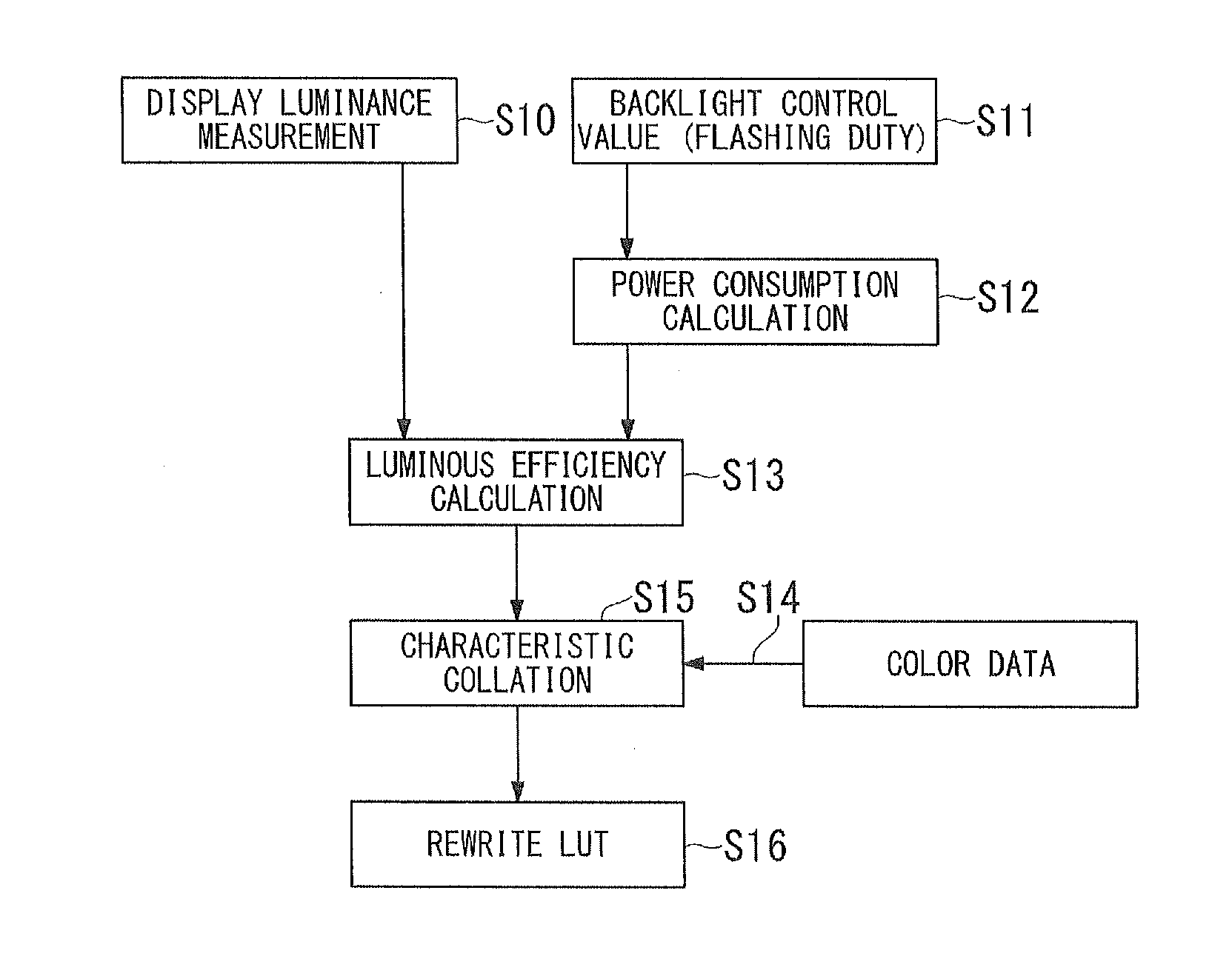
[0018]FIG. 1 is a block diagram showing the configuration of a display device according to one embodiment of this invention. A display panel 10 displays an image in response to a video signal input thereto. A backlight 11 irradiates light to illuminate the display panel 10. A backlight power detector 12 detects electrical power driving the backlight 11. It is possible to detect the drive power which is calculated based on a characteristic measured in advance by use of a control value of a light source (e.g. flashing duty, voltage, or current). Herein, the backlight power detector 12 may store a control value and drive power, related to the control value, in a memory device. Upon detecting a control value, it may read the drive power, corresponding to the control value, from the memory device.

[0019]A control value of a light source (e.g. flashing d...


PUM

PropertyMeasurementUnit
electricalaaaaaaaaaa
luminanceaaaaaaaaaa
luminous efficiencyaaaaaaaaaa

Abstract

A display device includes a backlight power detector for detecting electrical power driving a backlight; a luminance detector for detecting luminance of a display panel; a luminous efficiency chromaticity storage unit for storing the relationship between display chromaticity and a luminous efficiency calculated based on display luminance and backlight power; and a chromaticity correction device for calculating a luminous efficiency based on the detection result of the backlight power detector and the detection result of the display luminance detector, for reading the display chromaticity, corresponding to the calculated luminous efficiency, from the luminous efficiency chromaticity storage unit, and for correcting the display chromaticity of a video signal, thus matching the display chromaticity displayed on the display panel with the read display chromaticity.

Description

TECHNICAL FIELD[0001]The present invention relates to a display device, which corrects chromaticity of an image displayed on a display panel, and a color-correction method for a display device.BACKGROUND ART[0002]Display devices may undergo variations of display colors due to ambient environments. For this reason, it is necessary to carry out a purpose of suppressing variations of display colors by way of a generally-known technique in which a display device is equipped with a temperature sensor for detecting its temperature so as to correct a display color based on the detected value of the temperature sensor (hereinafter, referred to steady correction). In particular, it is necessary to implement periodic correction for display devices in industrial fields requiring strict color reproduction. Patent Literatures 1, 2 are well known as technologies for correcting chromaticity (i.e. viewers' coloration).[0003]With the steady correction, however, it is impossible to precisely correct ...

Claims


Application Information

Patent Timeline
Patent Type & Authority Applications(United States)
IPC IPC(8): G09G5/02
CPCG09G5/02G09G3/2003G09G3/3406G09G2320/0242G09G2320/0666G09G2330/02G09G2360/145G09G2360/16
Inventor FUJIMURA, RYUUICHIMATSUI, KATSUYUKI
Owner NEC DISPLAY SOLUTIONS LTD
Why Eureka
Try Eureka