Display unit

a display unit and display technology, applied in the field of display units, can solve the problems of increasing power consumption and enormous number of matrix operations, and achieve the effects of less calculations, less calculations, and reduced number of matrix operations required for calculations to correct variations in luminance and chromaticity

Inactive Publication Date: 2010-01-07
SONY SEMICON SOLUTIONS CORP
View PDF30 Cites 12 Cited by
  • Summary
  • Abstract
  • Description
  • Claims
  • Application Information

AI Technical Summary

Benefits of technology

[0013]According to the embodiment of the present invention, each of elements of coefficient matrixes necessary to perform calculations for correcting the luminance and chromaticity is assigned a necessary number of bits. As a result, the whole bit number is reduced so that the same correction effect can be obtained with less calculations.
[0014]According to the embodiment of the present invention, the number of matrix operations required for calculations for correcting variations in luminance and chromaticity is reduced so that the same correction effect can be obtained with less calculations. This can eliminate the need to use a memory operable at higher speed than required, as well as can reduce power consumption.

Problems solved by technology

However, if the number of pixels included in the display unit is increased, an enormous number of matrix operations have to be performed.
As a result, the following problems occur.
(2) About 120,000,000 3×3 matrix operations are performed per second, so power consumption is increased.

Method used


Image

  • Display unit
  • Display unit
  • Display unit

Examples


application example

[0067

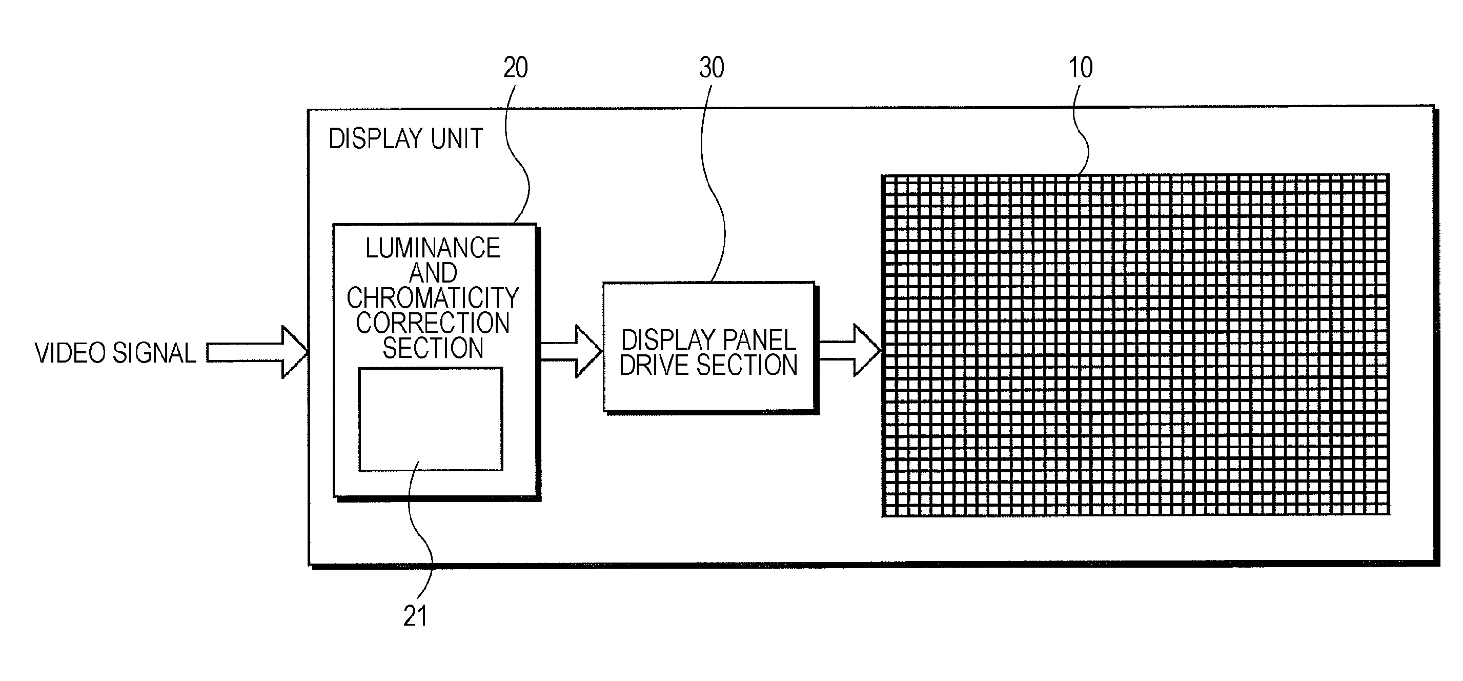
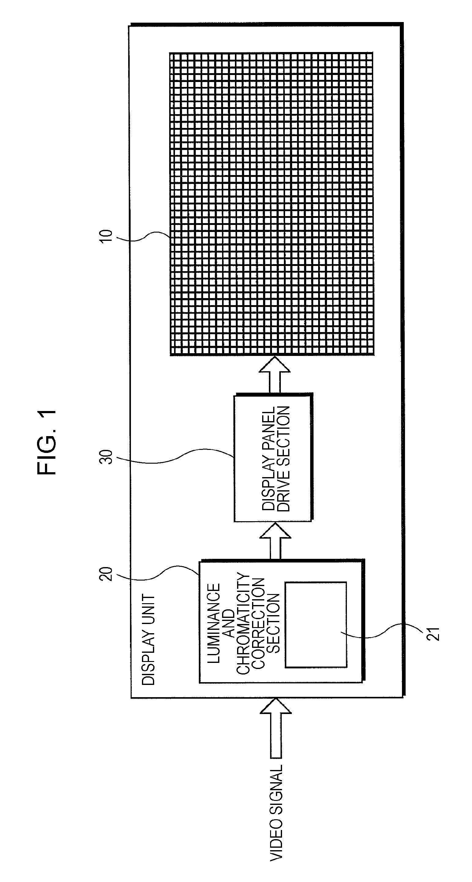
[0068]A SPAM (static random access memory) may be used as the storage section for storing matrix data, of the luminance and chromaticity correction section shown in FIG. 1 and a non-volatile memory may be added separately. Thus, matrix data is transferred from the non-volatile memory to the SRAM when the display unit is started. In this case, the sizes of the two memories, SRAM and non-volatile memory, are reduced.

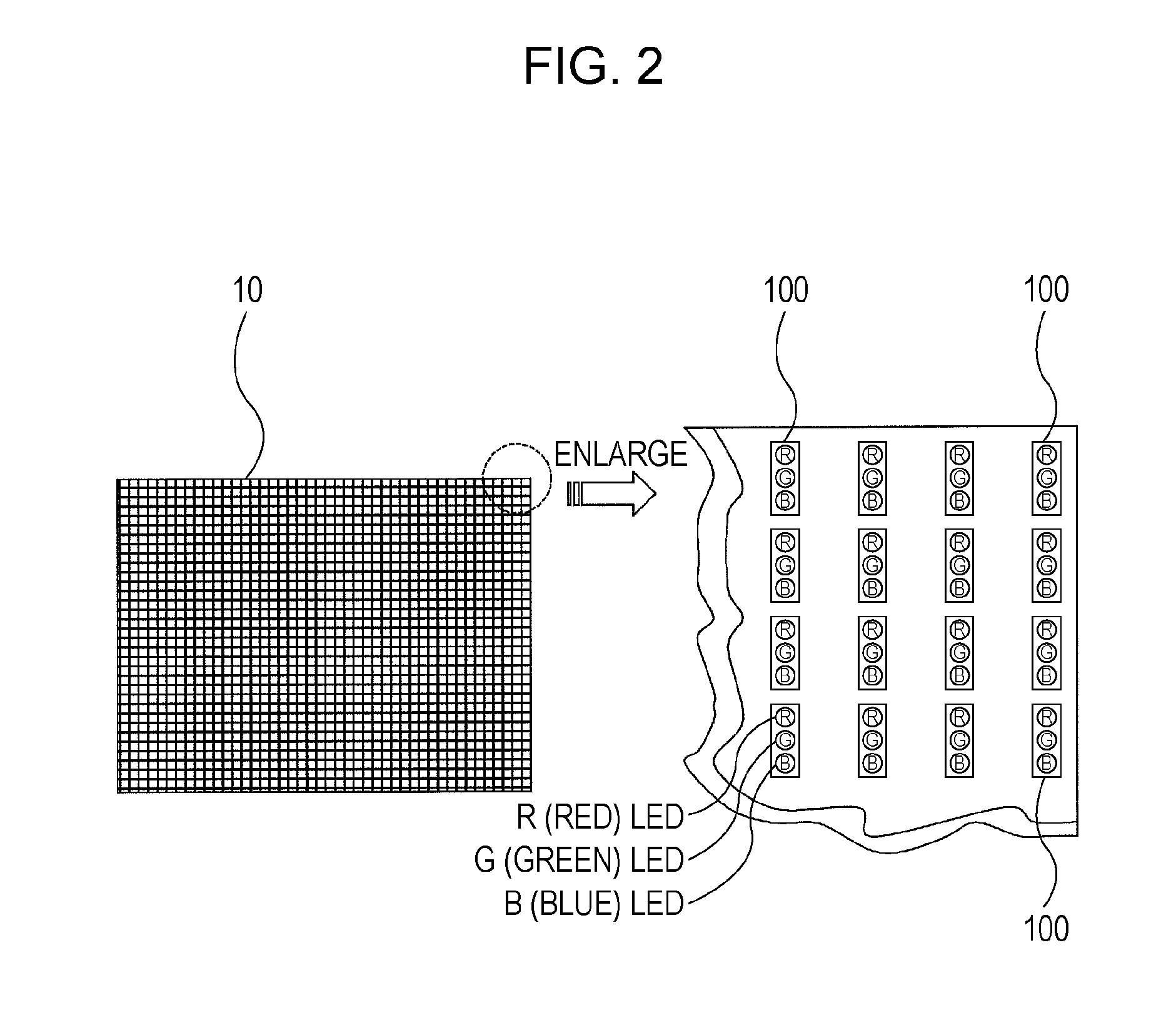
[0069]Also, the light-emitting devices included in the pixels of the display panel are not limited to LEDs and may be other light-emitting devices such as organic EL (electroluminescence) devices. Also, the colors of the light-emitting devices included in the pixels are not limited to the three colors, R, G, and B. Four or more colors including at least one of R, G, and B may be used or other colors may be used. In this case, matrix data having a matrix corresponding to the number of light-emitting devices included in one pixel is used.

[0070]Advantages of Embodiment

[0...


PUM


Abstract

A display unit includes: a display section including a plurality of pixels, each of the pixels including a plurality of light-emitting devices; an operation section that performs calculations for correcting drive signals to be inputted into the light-emitting devices of the pixels included in the display section in order to correct luminances and chromaticities of the pixels; and a coefficient data input section where a bit number of an element having smaller variations in coefficient in the display section, among elements of each of coefficient matrixes necessary for the correction calculations, the coefficient matrixes to be inputted into the operation section, is set to a value smaller than a bit number of an element having larger variations.

Description

BACKGROUND OF THE INVENTION[0001]1. Field of the Invention[0002]The present invention relates to a display unit that displays images by controlling multiple light-emitting devices included in each pixel using video signals.[0003]2. Description of the Related Art[0004]In a color display unit that includes an array of light-emitting devices, such as LEDs (light-emitting diodes), and makes fine display by driving the light-emitting devices individually, the luminance and chromaticity vary among the pixels due to such as manufacturing variations in the light-emitting devices even if same video signals are inputted into the light-emitting devices. As a result, the image quality is reduced. For this reason, there has been presented a method of correcting signals to be inputted into the light-emitting devices by performing 3×3-matrix operations on the video signals, as disposed in Japanese Unexamined Patent Application Publication Nos. 2000-155548 and 2001-188513.[0005]The above-mentioned ...

Claims


Application Information

Patent Timeline
Patent Type & Authority Applications(United States)
IPC IPC(8): G09G5/10
CPCG09G3/30G09G2320/0233G09G2320/0242G09G2340/0428G09G2320/0666G09G2320/0693G09G2330/021G09G2320/0285
Inventor TOBITA, HIROSHIMISONOU, TAKEHIRO
Owner SONY SEMICON SOLUTIONS CORP
Why Eureka
Try Eureka