Method for determining the oil temperature in an internal combustion engine

a technology of internal combustion engine and oil temperature sensor, which is applied in the direction of machines/engines, analogue processes for specific applications, instruments, etc., can solve the problems of inability to provide a precise value for the oil temperature and inaccurate oil temperature determination by means of the oil temperature sensor, and achieve the effect of accurate approximation

Inactive Publication Date: 2006-06-27
SIEMENS AG
View PDF13 Cites 9 Cited by
  • Summary
  • Abstract
  • Description
  • Claims
  • Application Information

AI Technical Summary

Benefits of technology

[0015]This enables the oil temperature sensor value of the model to be rapidly approximated to the oil temperature value of the sensor by suitable selection of the mathematical computation rule with which the differential value is incorporated in the oil temperature model and therefore means that fewer calculation cycles are necessary in the model for a sufficiently accurate approximation of the two oil temperature values.

Problems solved by technology

However, determining the oil temperature by means of the oil temperature sensor is very inaccurate, particularly in the warm-up phase of the oil when the internal combustion engine is not at normal operating temperature.
However, all these methods are unable to provide a precise value for the oil temperature.

Method used


Image

  • Method for determining the oil temperature in an internal combustion engine
  • Method for determining the oil temperature in an internal combustion engine
  • Method for determining the oil temperature in an internal combustion engine

Examples


Embodiment Construction

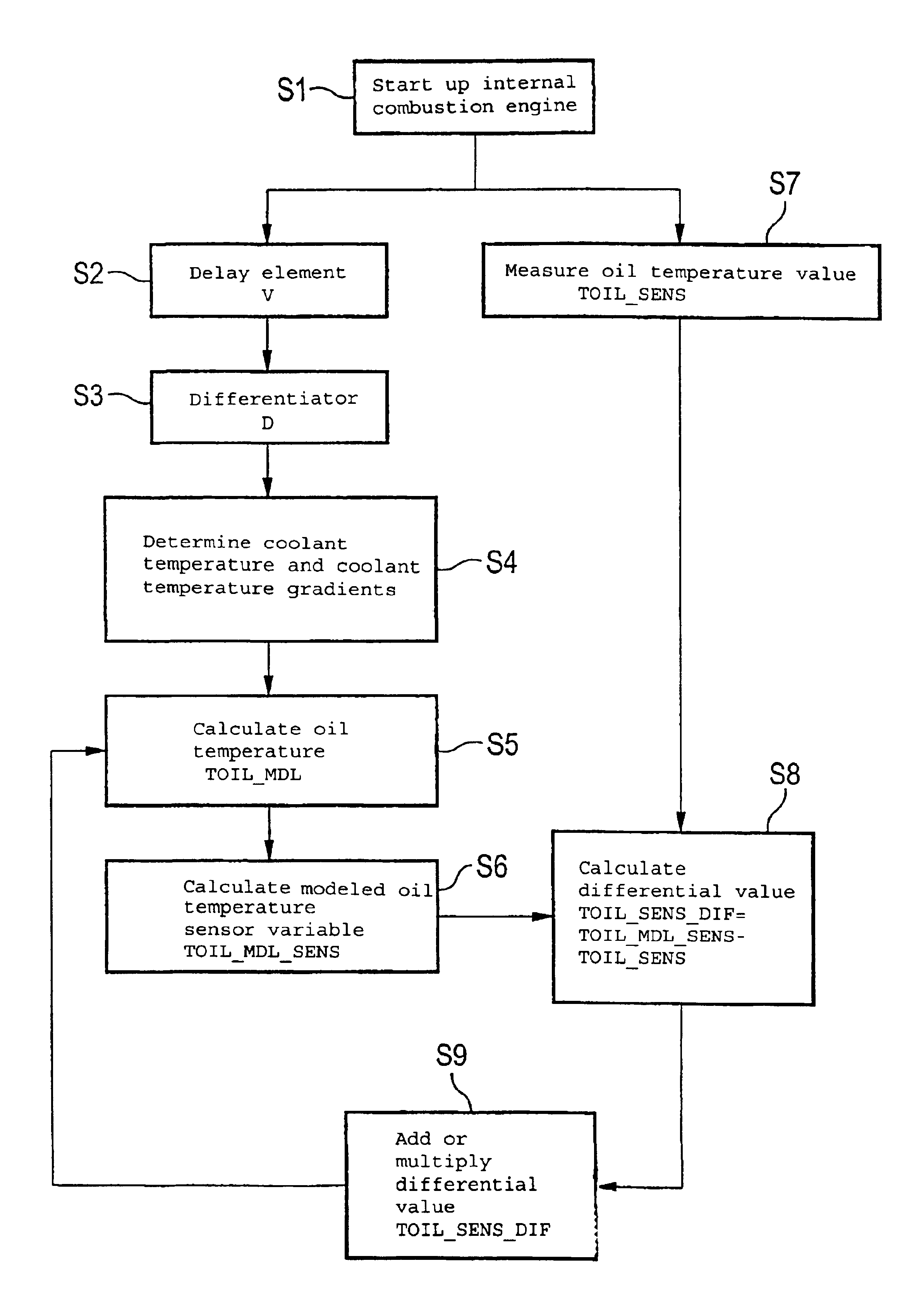
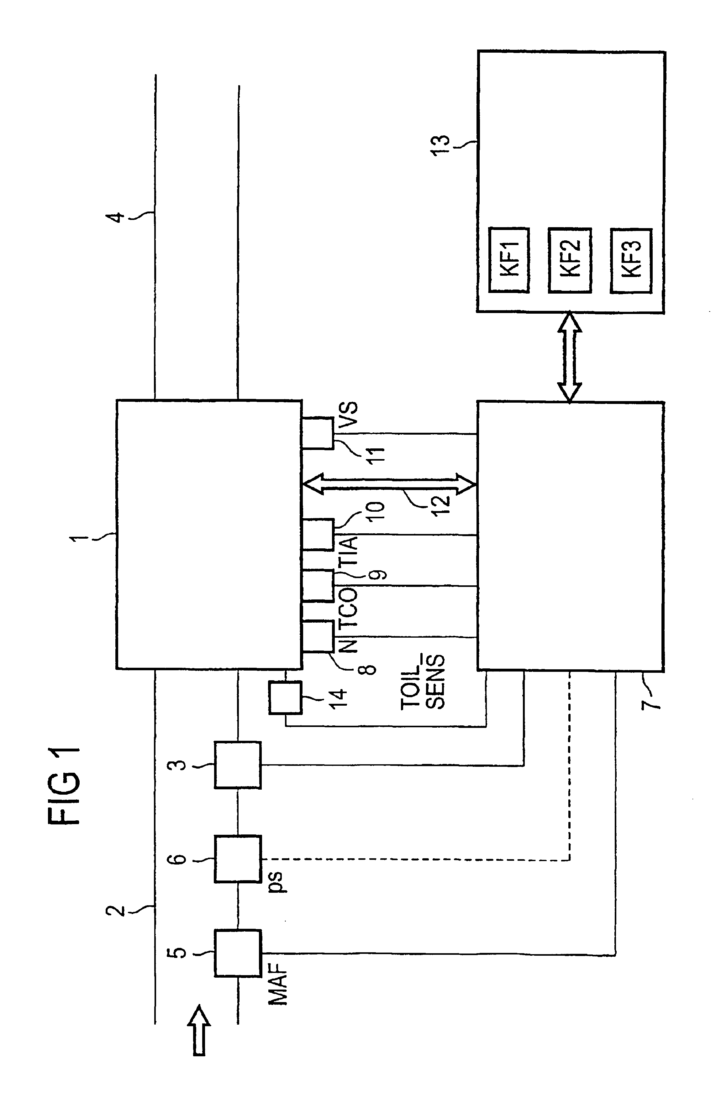
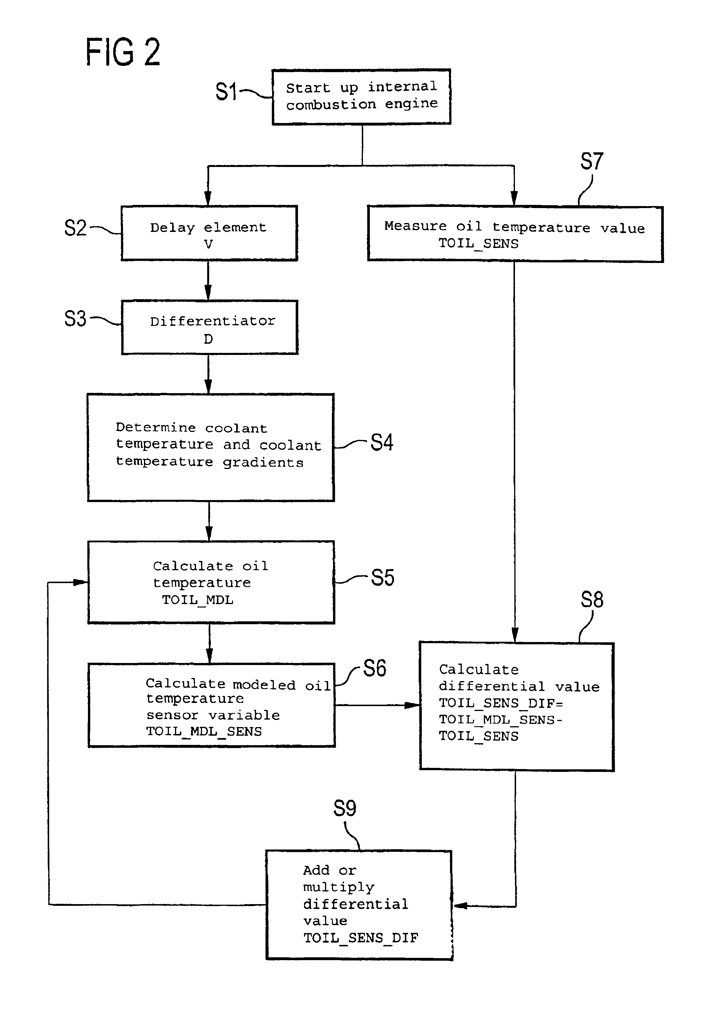
[0025]FIG. 1 is a very simplified representation of an internal combustion engine with control unit, only the parts necessary for understanding the invention being illustrated.

[0026]The internal combustion engine 1 preferably used as the propulsion source for a motor vehicle is supplied with the air necessary for combustion via an intake manifold 2. An injection system 3 injects fuel into the intake manifold 2. However, the method according to the invention can also be used for an internal combustion engine with fuel direct injection having, for example, a high-pressure reservoir (common rail) injection system with injection valves which spray the fuel directly into the cylinders of the internal combustion engine 1. The exhaust gas of the internal combustion engine 1 flows via an exhaust manifold 4 to an exhaust treatment system and from there to the open air via a muffler (not shown).

[0027]In the intake manifold 2 there is provided a load sensor in the form of an air mass sensor 5 ...


PUM


Abstract

The oil temperature in the internal combustion engine is calculated using an oil temperature model, which draws upon at least one parameter that characterizes the operating point of the internal combustion engine. The differential value between the modeled temperature value of the oil temperature model and the measured temperature value of the oil, which is measured by the oil temperature sensor, is included as an input variable in the oil temperature model during an iterative calculation cycle of an oil temperature value of the oil temperature mode, said calculation cycle directly or indirectly following the method step involving the calculation of the differential value.

Description

PRIORITY CLAIM[0001]This is a U.S. national stage of application No. PCT / DE02 / 01231, filed on 04 Apr. 2002. Priority is claimed on that application and on the following application(s): Country: Germany, Application No.: 101 19 786.1, Filed: 23 Apr. 2001.BACKGROUND OF THE INVENTION[0002]1. Field of the Invention[0003]The invention relates to a method for determining the oil temperature in an internal combustion engine.[0004]2. Description of the Prior Art[0005]The current temperature of the engine oil is required for certain functions in an electronic control system for internal combustion engines. For example, the exceeding of a threshold value for the oil temperature of the engine can be used to trigger on-board diagnostics. Another known use of the oil temperature is as a criterion for adjusting the idling speed of an internal combustion engine, as at very high oil temperatures a higher idling speed is necessary in order to provide the internal combustion engine with an adequate s...

Claims


Application Information

Patent Timeline
Patent Type & Authority Patents(United States)
IPC IPC(8): F01M5/00F01M1/18F01M11/10
CPCF01M1/18F01M11/10F01M5/005F02D2200/023
Inventor KUNZ, FRANZZHANG, HONG
Owner SIEMENS AG
Why Eureka
Try Eureka