Display apparatus and correction method

a technology of display apparatus and correction method, which is applied in the direction of electroluminescent light sources, static indicating devices, instruments, etc., can solve the problems of difficulty in displaying an exact color, difference in color between tiled units, and image quality degradation, so as to reduce the variation in chromaticity and correct luminance and chromaticity, the effect of easy visual recognition

Active Publication Date: 2020-05-19
SONY SEMICON SOLUTIONS CORP
View PDF21 Cites 2 Cited by
  • Summary
  • Abstract
  • Description
  • Claims
  • Application Information

AI Technical Summary

Benefits of technology

[0016]In the first display apparatus and the first correction method according to the embodiments of the disclosure, in order to correct the luminance and the chromaticity of the first primary color, the correction factor determined by adjusting the light emission intensity ratios of the light-emitting devices of the first primary color provided in two or more pixels is used. In a case where the luminance and the chromaticity of the first primary color are corrected by adding other primary colors by, for example, the additive mixing, using the correction factor makes it possible to reduce variation in chromaticity that is easily visually recognized in the center section of the retina of the human eye. This makes it possible to improve image quality.
[0017]In the second display apparatus and the second correction method according to the embodiments of the disclosure, the luminance of the first primary color is corrected in each of the pixels, and the chromaticity of the first primary color is corrected with use of the correction factor determined, based on the chromaticities of the light-emitting devices of the first primary color provided in two or more pixels. This makes it possible to reduce the occurrence of the phenomenon in which hues and brightness differ by the visual field. This makes it possible to improve image quality.
[0018]It is to be noted that the above description is merely examples of the embodiments of the disclosure. Effects of the embodiments of the disclosure are not limited to effects described here, and may be different from the effects described here or may further include any other effect.
[0019]It is to be understood that both the foregoing general description and the following detailed description are exemplary, and are intended to provide further explanation of the technology as claimed.

Problems solved by technology

When LEDs that vary in wavelength and chromaticity are provided in respective pixels, it may be difficult to match colors of the respective pixels, thereby causing degradation in image quality such as rough display, the occurrence of color unevenness in a display screen, a difference in color between tiled units, and difficulty in displaying an exact color.

Method used


Image

  • Display apparatus and correction method
  • Display apparatus and correction method
  • Display apparatus and correction method

Examples


first embodiment

[0068](Configuration)

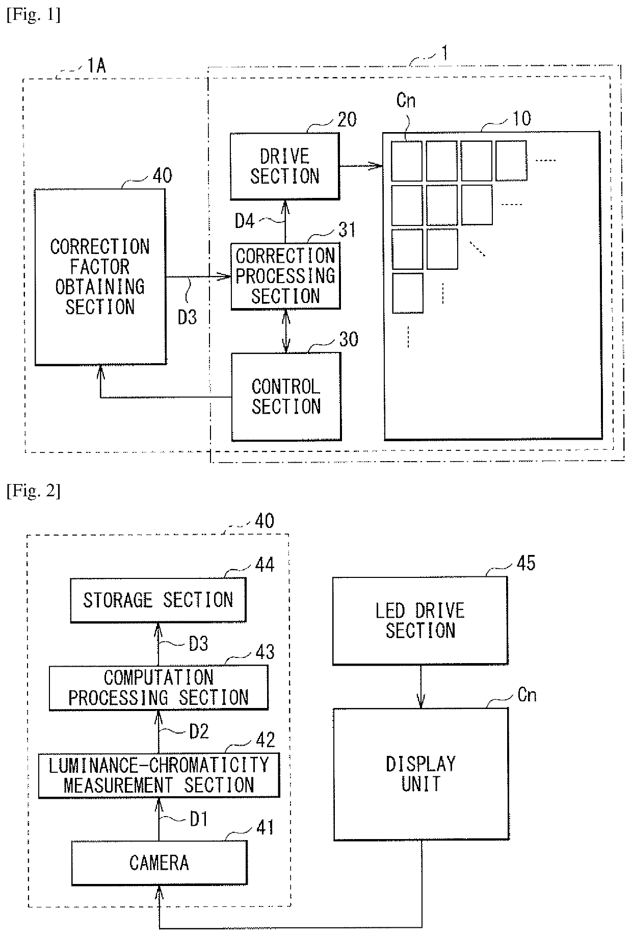
[0069]FIG. 1 illustrates an example of an entire configuration of a display apparatus (a display apparatus 1) according to a first embodiment of the disclosure. The display apparatus 1 may include, for example, a display section 10, a drive section 20, a control section 30, and a correction processing section 31. The display section 10 may include, for example, a plurality of display units Cn. It is to be noted that the drive section 20, the control section 30, and the correction processing section 31 correspond to specific examples of “drive section” in an embodiment of the disclosure.

[0070]The display section 10 may be configured of, for example, a combination of the plurality of display units Cn. The plurality of display units Cn are two-dimensionally arranged in the display section 10. Each of the plurality of display units Cn may include, for example, a plurality of pixels arranged in a matrix. Light-emitting devices corresponding to three primary colors ar...

second embodiment

[0108]FIG. 20 is an example of a pixel array in a display section of a display apparatus according to a second embodiment of the disclosure. In the foregoing first embodiment, the light emission intensity ratios of blue are adjusted in the assemblies U1 in each of the display units Cn to correct luminance and chromaticity. In this embodiment, a correction factor is determined at least in each combination of adjacent display units Cn, and luminance and chromaticity is corrected with use of the determined correction factor.

[0109]More specifically, in this embodiment, as illustrated in FIG. 20, it is assumed that a blue LED 10B5 provided in each pixel P1 of a display unit C1 and a blue LED 10B6 provided in each pixel P2 of a display unit C2 are different in wavelength from each other. In the display units C1 and C2, the red LEDs 10R have an equal wavelength, and the green LEDs 10G have an equal wavelength.

[0110]In this embodiment, when variation in wavelength occurs between the blue LE...

third embodiment

[0122]FIG. 31 is a chromaticity diagram for describing a correction factor used in a display apparatus according to a third embodiment of the disclosure. FIG. 32 is a chromaticity diagram for describing a correction factor according to a comparative example.

[0123]In this embodiment, in a case where blue LEDs that vary in wavelength between pixels or between display units are provided, luminance and chromaticity of blue are corrected. In this embodiment, the luminance of blue is corrected in each pixel. The chromaticity of blue is corrected with use of a correction factor determined, based on each of chromaticities of the blue LEDs in the assembly U1.

[0124]More specifically, as illustrated in FIG. 31, the chromaticity of blue is adjusted by determining an average value of the chromaticites of a pixel A corresponding to a long wavelength and a pixel B corresponding to a short wavelength and shifting chromaticity points of the pixels A and B to a target correction point P4 with use of ...


PUM


Abstract

A display apparatus may comprise a display section and circuitry. The display section may comprise a plurality of display units arranged in a two-dimensional array, wherein each of the display units comprises a plurality of pixels arranged in a matrix, and each of the plurality pixels comprises a plurality of light-emitting devices that are each configured to emit a different color of light. The circuitry may be configured to generate a corrected image signal based on an uncorrected image signal and correction factors that correct luminance and chromaticity of the light-emitting devices, including at least some correction factors determined by adjusting light emission intensity ratios of first light-emitting devices that are configured to emit light of a particular color and are disposed in different ones of the plurality of pixels.

Description

CROSS-REFERENCE TO RELATED APPLICATIONS[0001]This application is a National Stage of International Application No. PCT / JP2016 / 000791, filed in the Japanese Patent Office as a Receiving office on. Feb. 16, 2016, which claims priority to Japanese Patent Application Number 2015-053462, filed in the Japanese Patent Office on Mar. 17, 2015, the entire contents of each of which are incorporated herein by reference,TECHNICAL FIELD[0002]The disclosure relates to a display apparatus including light-emitting devices corresponding to three primary colors in a pixel, and a correction method.BACKGROUND ART[0003]For example, as display apparatuses using three primary colors such as R (red), G (green), and B (blue), LED displays using light-emitting diodes (LEDs) have been developed. The LED displays have high luminance and high color purity. The LED displays utilizing characteristics of an LED light source as a point light source are frequently used as indoor and outdoor large displays. Most of t...

Claims


Application Information

Patent Timeline
Patent Type & Authority Patents(United States)
IPC IPC(8): G09G3/20G09G3/32G09G5/02H05B44/00
CPCG09G3/2003G09G3/32G09G2320/0242G09G5/02G09G2320/0666G09G2300/026G09G2320/0285G09G2360/16G09G2300/0452G09G2360/142G09G2320/0693
Inventor BIWA, GOSHIKIKUCHI, NORIFUMINISHINAKA, IPPEI
Owner SONY SEMICON SOLUTIONS CORP
Why Eureka
Try Eureka