Device for controlling light emission rates of a backlight

a technology of light emission rate and backlight, which is applied in the direction of electric variable regulation, process and machine control, instruments, etc., can solve the problems of difficult to determine if the change is attributable to the termination service life, the junction temperature or the external environment, etc., and achieves simple feedback and little temperature changes.

Inactive Publication Date: 2007-02-13
SONY CORP
View PDF4 Cites 32 Cited by
  • Summary
  • Abstract
  • Description
  • Claims
  • Application Information

AI Technical Summary

Benefits of technology

[0018]In view of the above-identified problem of the related art, it is therefore desirable to provide a control device of a backlight unit that can stably correct the chromaticity of the LED backlight of the backlight unit by means of a simple arrangement.
[0023]Thus, a control device according to the invention can conduct a feedback operation on the electric current supplied to the red LEDs and the green LEDs according to the detection output of the optical sensor for the blue LEDs by maintaining the electric current supplied to the blue LEDs that show relatively little temperature changes to a constant level and hence can be used to form a simple feedback system.

Problems solved by technology

Meanwhile, when the light emission efficiency of LEDs of green color changes, it is difficult to determine if the change is attributable to the terminating service life, the change in the junction temperature or the external environment.

Method used


Image

  • Device for controlling light emission rates of a backlight
  • Device for controlling light emission rates of a backlight
  • Device for controlling light emission rates of a backlight

Examples


Embodiment Construction

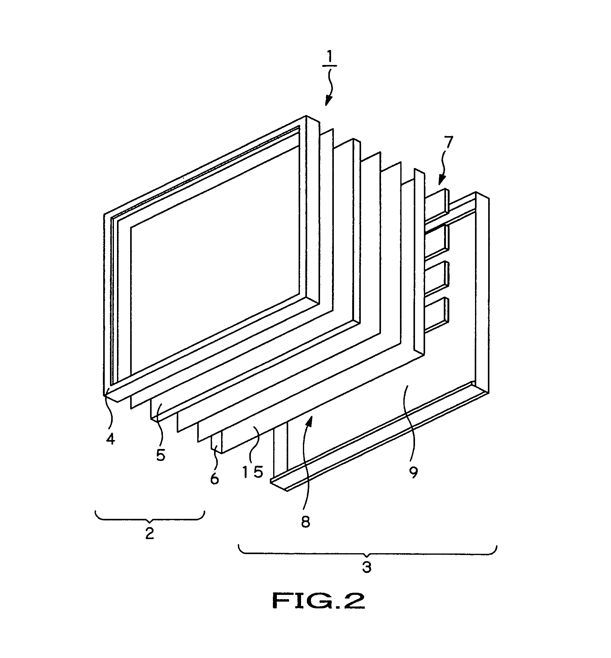
[0032]Now, the present invention will be described by referring to the accompanying drawings that illustrates a preferred embodiment of a control device according to the invention that is installed in a transmission-type liquid crystal display panel. The transmission-type liquid crystal display panel 1 is used in a television set having a large display screen that is typically not smaller than 40 inches. Referring to FIGS. 2 and 4, the transmission-type liquid crystal display panel 1 comprises a liquid crystal panel unit 2 and a backlight unit 3 fitted to the rear side of the liquid crystal panel unit 2 to supply display light to the panel unit 2. The liquid crystal panel unit 2 includes a front frame member 4, a liquid crystal panel 5, and a rear frame member 6, the front frame member 4 and the rear frame member 6 being adapted to hold the liquid crystal panel 5 along the outer peripheral edges thereof by pinching it between them by way of spacers 2A, 2B and guide members 2C.

[0033]...


PUM


Abstract

A control device can stably control the quantity of the emitted light of a backlight unit by means of a simple arrangement. The control device comprises an electric current supply section for supplying a predetermined drive current to a group of light emitting elements, a quantity of emitted light detecting section for detecting the quantity of light emitted from the group of light emitting elements, a temperature detecting section for detecting the temperature of the backlight unit, a reference quantity of light outputting section for outputting a reference quantity of light for the light emitting elements of each color and a control section for controlling the electric current supply section so as to make it supply a constant drive current to the light emitting elements of blue color according to the quantity of emitted light detected by the quantity of emitted light detecting section, the temperature detected by the temperature detecting section, and the reference quantity of light output from the reference quantity of light outputting section and supply a predetermined drive current to the light emitting elements of red color and those of green color according to the constant drive current supplied to the light emitting elements of blue color.

Description

CROSS REFERENCES TO RELATED APPLICATIONS[0001]The present invention contains subject matter related to Japanese Patent Application JP 2004-238790 filed in the Japanese Patent Office on Aug. 18, 2004, the entire contents of which are incorporated herein by reference.BACKGROUND OF THE INVENTION[0002]1. Field of the Invention[0003]The present invention relates to a control device that is installed in a liquid crystal display apparatus and the like and that controls the light emission rate of the backlight thereof.[0004]2. Description of the Related Arts[0005]Like self-emission-type PDPs (plasma display panels), liquid crystal display apparatuses are being popularly used in television sets and various displays because they can provide a large display screen and have many other advantages, such as being lightweight, thin and of a low power consumption rate when compared with display apparatuses comprising a CRT (cathode ray tube). A liquid crystal display apparatus has a pair of transpar...

Claims


Application Information

Patent Timeline
Patent Type & Authority Patents(United States)
IPC IPC(8): H05B37/02G09G3/34H05B44/00
CPCG09G3/3413H05B33/0872H05B33/0869G09G2320/041G09G2320/043G09G2320/0606G09G2320/0666G09G2320/08G09G2360/145G09G2320/0626H05B45/28G02F1/133H05B45/22
Inventor TAGAWA, YASUHIRO
Owner SONY CORP
Why Eureka
Try Eureka